Back to the tracer subject again! Today officially completed this project that I think took me 6 months at least. I completed the chassis (bottom plate was still missing) and here it is:
http://www.bartola.co.uk/valves/wp-content/gallery/curve-tracer_1/img_2995.jpg
An example of the 6e5p in triode mode:
http://www.bartola.co.uk/valves/wp-content/uploads/2012/05/6e5p-triode-2.jpg
Now time to trace some curves.
cheers,
Ale
http://www.bartola.co.uk/valves/wp-content/gallery/curve-tracer_1/img_2995.jpg
An example of the 6e5p in triode mode:
http://www.bartola.co.uk/valves/wp-content/uploads/2012/05/6e5p-triode-2.jpg
Now time to trace some curves.
cheers,
Ale
Congratulations!
Thanks. I may have to improve the PLL. When it get warm it drifts and require readjustment. Need an PLL expert to give me a hand here!
Very Nice Job Ale. Congrats.
Thanks Steven. Actually you made me start this project and helped me all along...
Ale, great job! See you have been busy tracing.
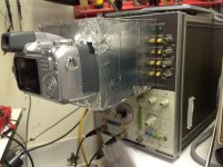
I built a camera hood that works great for me. It is made of 1/4 inch hard foam that is used for posters. The hood is light and strong and snaps tightly against the oscilloscope screen frame.
I built a camera hood that works great for me. It is made of 1/4 inch hard foam that is used for posters. The hood is light and strong and snaps tightly against the oscilloscope screen frame.
Attachments
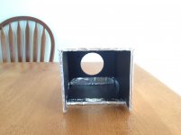
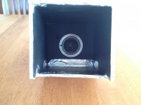
you'll improve the contrast of the pictures if you put some black tape over the foil facing the scope.
My Canon G12 has a "TV" setting which is useful when I pull pictures off the 576 curve tracer, 2465B or HP3577. You can then use "Graph Grabber" to obtain XY values for spice models. Much easier to use than my Fuji D-Cam.
My Canon G12 has a "TV" setting which is useful when I pull pictures off the 576 curve tracer, 2465B or HP3577. You can then use "Graph Grabber" to obtain XY values for spice models. Much easier to use than my Fuji D-Cam.
Alfredo,
That's great! How do you manage getting the right exposure with the camera hood? Can you get to see the screen grid lines well defined? please post some pictures of the results
thanks
ale
I had some pictures but they are gone
Murphy's law hit me last week. I gave my daughter a macbook as graduation present, she turned it on, the damned thing saw the Readynas Network Drive.... Ran the copy utility that comes with the mac against her old Notebook. But the Readynas drive appears automatically and had nothing to do with the copy. She figured the stuff wasn't hers, deleted it without asking She honestly thought it was on her local drive. Wiped out everything in the drive. Lots of it was being backed up daily to another drive, but my DIY working directory wasn't. Spend a full day trying to recover the lost data to no avail. Since it was deleted as a network drive there was no undelete. I purchased some recovery software but it didn't really help. I guess I learned a lesson.I will set the tracer back on the bench (working on something else) and get some pictures. Pretty sure I was using Aperture priority mode and there was a difference depending which oscilloscope I was using. For the curve tracing I have mostly been using the analog storage oscilloscope as it works like a charm. That one has more emitted light as it has no refresh problem and mostly I use the hood to get rid of nasty reflections from a upper garage door window in from of my bench. If I use the tek oscilloscope then I need to pay more attention to the settings.
I will get you some samples as soon as I can.
Alfredo
In this digital era a backup is mandatory, but we all learn it one way or another! Hope you haven't lost too much. Worst is when you lose pictures etc
Yes, reflections are horrible. I mostly taken most of my picture during the day and have a window as well on my attic just behind the oscilloscope. I guess that if I build a hood and is completely dark not sure if the grid lines will come up properly...will need to test
cheers
ale
Yes, reflections are horrible. I mostly taken most of my picture during the day and have a window as well on my attic just behind the oscilloscope. I guess that if I build a hood and is completely dark not sure if the grid lines will come up properly...will need to test
cheers
ale
you'll improve the contrast of the pictures if you put some black tape over the foil facing the scope.
My Canon G12 has a "TV" setting which is useful when I pull pictures off the 576 curve tracer, 2465B or HP3577. You can then use "Graph Grabber" to obtain XY values for spice models. Much easier to use than my Fuji D-Cam.
I have a G10 and it seems it doesn't have such feature.
I have to play around with the exposure and speed to ensure the refresh is not a problem. Unfortunately the phone camera is useless here as refresh is an issue.
you'll improve the contrast of the pictures if you put some black tape over the foil facing the scope.
Yes, the darker the better. Need to do that.
You can then use "Graph Grabber" to obtain XY values for spice models. Much easier to use than my Fuji D-Cam.
As an alternative you can use Engauge Digitizer. What I like about it is that when you export the data you can set it to extrapolate the y values from the x grid points. I take this data into program called Graph where I can easily draw load lines and plate dissipation curves.
Alfredo
Yes, the darker the better. Need to do that.
As an alternative you can use Engauge Digitizer. What I like about it is that when you export the data you can set it to extrapolate the y values from the x grid points. I take this data into program called Graph where I can easily draw load lines and plate dissipation curves.
Alfredo
Hi Alfredo,
Tried Engauge digitizer and is really easy to extract data for Excel, etc.
Which is the application "Graph" you are refering to draw loadlines, etc.?
I use Dmitry's tool to create SPICE models, and after a bit of practice you can create very accurate models...
Ale,
What did you end up for the current sense, is it just switchable 1R and 10R? And is the return of the sense resistor tied to one end of the rectifiers as Merlin suggested? Also, what're the Ia x1 and x10 switches on your control panel, is it a 10x voltage amp?
Thanks,
Jaz
What did you end up for the current sense, is it just switchable 1R and 10R? And is the return of the sense resistor tied to one end of the rectifiers as Merlin suggested? Also, what're the Ia x1 and x10 switches on your control panel, is it a 10x voltage amp?
Thanks,
Jaz
Ale,
What did you end up for the current sense, is it just switchable 1R and 10R? And is the return of the sense resistor tied to one end of the rectifiers as Merlin suggested? Also, what're the Ia x1 and x10 switches on your control panel, is it a 10x voltage amp?
Thanks,
Jaz
Hi Jaz,
Yes, current sensing is 1R and 10R. Typically I use 1R for most valves, unless testing low current / low transconductance valves as 10R may be better subject to scope input sensitivity and environment noise. 90% of the time I use 1R, but at some points during the day I switch to 10R given mains noise, etc.
Havent implemented return as Merlin suggested, a very good idea though.
x1/x10 switch is for my diff amp picking up the voltage across the sensing resistor. I had this circuit build beforehand so reused it here. It gives more flexibility to use the tracer with any oscilloscope...
Keep posted on progress!!
Cheers,
Ale
Will do, I am still debating if I should use my tube tester as the "platform" and just build the grid drive circuit, or go for a scratch build...
Thanks,
Jaz
Will do, I am still debating if I should use my tube tester as the "platform" and just build the grid drive circuit, or go for a scratch build...
Thanks,
Jaz
Tube tester has a "short" test which is the first test you should (always) perform!
I just got an Arduino Leonardo which is going to form the basis of a new, open source, tube and transistor tester.
Which is the application "Graph" you are refering to draw loadlines, etc.?
My apologies Ale, never saw the notification for this post.
This is the link to the Graph application Download | Graph
Alfredo
Tube tester has a "short" test which is the first test you should (always) perform!
I just got an Arduino Leonardo which is going to form the basis of a new, open source, tube and transistor tester.
Yes, agreed. I'm thinking of adding either a classic neon testing point or a transistor sensing circuit similar to the Sussex valve tester. I do have a tester, but is always handy to identify leakage before attempting any curve tracing work
RE Arduino, that is a great option and would be great to hear progress on that!
Ale
My apologies Ale, never saw the notification for this post.
This is the link to the Graph application Download | Graph
Alfredo
Thanks Alfredo, will look at this!
- Status
- This old topic is closed. If you want to reopen this topic, contact a moderator using the "Report Post" button.
- Home
- Design & Build
- Equipment & Tools
- DIY Curve Tracer