Thanks Ale.
None of my transformers are back to back. They do share the bias voltage that i am injecting via the center taps. I want to draw the schematic and post it. What software do you use?
Now that you are running at 200hz you could use the 4th bit on the clock and get 16 steps.
Been reading lots of posts on the 4p1l. May need to get some of those. I have been testing cheap tv tubes i got for $1 and dont mind ruining a few. A while back I did build a trioded pp amp for my dad using the 6eb8 and cheap speco 7010 transformers and it sounded fantastic. http://www.diyaudio.com/forums/tubes-valves/71300-photo-gallery-55.html#post2041734
I took everything apart yesterday and I am trying to figure out how to stuff it all into a case i found. My original thought was to use an old tube tester as platform but i am changing my mind. I may go with adaptor modules that i plug into the chassis. I need to go to my surplus store to see if i find a generic male/ female plug/sockets with at least 12 connectors (to support compactrons, have a bunch). Will take pictures of the build.
Alfredo
Finally sorted the issue with the PLL locking. Tried all suggestions and still got the issue until I realised that the issue was impacted by the type DUT and current dragged by it. So found out that the back to back voltage sagging was impacting the clock and it seemed so obvious that why I didn't look to that before!
Anyway, added a simple 6V transformer to feed the PLL clock signal and now works like a charm.
What I found with tubes such as 6N7 and other ones that needed to remove the grid resistor (10-200K) to avoid double tracing and some oscillation. Tried all sorts of tubes with different GMs, power tubes, triode strapped, etc. and it seems like it works better for me without the grid resistor. Weird, but it does...
Regarding cad software i'm using an old coreldraw which is a pain in the back although the diagrams look neat. You may want to look for much better options out there...
Just ordered a couple of 230/230V toroid trafos to use as the main supply for the anode circuit and that should work fine...
Started thinking about the chassis and want to use the similar concept as my breadboard box with all the plugs as in the attached
Attachments
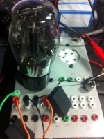
Glad to hear that your clock issues got resolved. I want to do something similar to what you have done with your breadboard. If I find some good 12 pin male/female plug and connector then I would build different adapters for the various socket types. I am also planning to buy some ferrite beads to put on the wires connecting the the adapters.
I found this case at my local surplus store.
I am planning to put one digital panel meter for the filament voltage and one for the screen supply fed from an external regulated supply.
Over the weekend I assembled the Variable HV supply. It is a variac connected to a 1050V CT transformer (rated at 250ma) Voltages show are RMS.
This will be the heater supply. Internally it has three 6.3V 4 amp series connected filament transformers.
I found this case at my local surplus store.
An externally hosted image should be here but it was not working when we last tested it.
I am planning to put one digital panel meter for the filament voltage and one for the screen supply fed from an external regulated supply.
An externally hosted image should be here but it was not working when we last tested it.
Over the weekend I assembled the Variable HV supply. It is a variac connected to a 1050V CT transformer (rated at 250ma) Voltages show are RMS.
An externally hosted image should be here but it was not working when we last tested it.
This will be the heater supply. Internally it has three 6.3V 4 amp series connected filament transformers.
An externally hosted image should be here but it was not working when we last tested it.
Alfredo,
It's looking terrific, well done. I wish mine ends up looking like that. I want to add a couple of more functionalities to my curve tracer as I'm going to drill so many holes for multiple sockets, so probably will add the capability to measure gm with an active load (e.g. gyrator/CCS) and simple leverage the existing power supplies with a simple addition of a couple of LCD meters.
Have been tracing many valves over the last weekend and found interestingly that not always the grid stopper (usually 10K) was effective. In some cases had to remove it, so probably may add a switch to bypass the grid stopper resistor, what do you think?
In the cases that the grid stopper didn't work, I got a slight double trace and it was gone once the grid stopper was removed.
I have also traced the famous GU-50 in triode strapped. Just used for the first time an 230/230V 80VA toroid I purchased early this week:
My Photos
Cheers,
Ale
Hi Ale,
Thanks.
Your curves look great, very clean. I guess you never needed the phase adjustment. On mine i do need it to clean the curves up. On my curves, if the phase is not adjusted I don't get a straight "series resistance" load line on the tips of the curves.
As far as the grid stopper go, i have been debating the same thing myself. The largest I have used is 1K. I was thinking of using a switch to select short,100,1000 and binding post so I can have flexibility.
As mentioned, I want to try some ferrite beads. I never used them before so I don't know if it will make a big difference.
I have not been able to find a good solution for multi pin male/female connectors so I might end up putting one of each socket.
I hope I can have some progress this weekend.
Alfredo
I cant sync better the curves as shown. Specially at the end of the curve I cant get rid of the retrace. But overall is ok and I'm a happy man.
Ferrite beads are good, I have a bunch of them but your idea is probably the best. I will add a selector switch with a set of none, 10, 100, 1k and 10k grid stoppers. Sounds like a plan.
I will try to post updated diagrams over the weekend.
Challenging tubes are high gm ones. Those are the ones to play with and see the results")
Cheers,
Ale
Ferrite beads are good, I have a bunch of them but your idea is probably the best. I will add a selector switch with a set of none, 10, 100, 1k and 10k grid stoppers. Sounds like a plan.
I will try to post updated diagrams over the weekend.
Challenging tubes are high gm ones. Those are the ones to play with and see the results
Cheers,
Ale
ALfredo,
Do you want a challenge? Try tracing a 6e5P in triode mode! That's a pain in the back. Had to ground a filament end to stop oscilation as there was no grid stopper capable of doing the job! I know that my breadboard setup is not ideal (long cables, etc.) but haven't had a similar challenge with other pentode triode strapped or a high mu triode such as 6s45p.
Some latest traces here:
My Photos
cheers,
Ale
As haven't started with the curve tracer chassis yet, I've been thinking in a small addition to the whole tester/tracer. It seems to me a waste of valve connectors not adding a simple test gig in addition to the curve tracer.
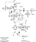
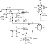
I usually measure valves distortion with a breadboarded jig and Pete Millet's audio interface to the PC. It works very nice, so I thought about the circuit drawn in the attached.
A simple jig with a grid voltage pot, a gyrator load, an anode current meter and a transconductance meter.
The jig uses the PC sound card to feed test signal and to measure (THD and THD/frequency). Transconductance is measured through a 200mV AC RMS meter as in the Sussex Valve Tester with the difference that the source test signal is provided by the PC: a 1kHz 100mV rms sine.
I think this could be a good addition to the tracer to measure:
1) valve operating points
2) Transconductance at operating point
3) THD
4) THD Frequency response
5) Mu
Thoughts? Any improvement suggestions?
Thanks
Ale
Attachments
Hi Ale,
You are building a super tester! How do you measure the DUT with PMillett's inteface? Is it a simple SE setup with a transformer?
Those russian tubes in your pictures look really good. Wish i had some. Yesterday a bought 11 6080 for $6 each. Have OTL in mind.
I have been thinking about the final chassis layout and i think i will include additional posts so I can also trace different feedback topologies, Schade, cathode, etc.. I am planning to do some work today......
Valve is loaded with a gyrator at the operating point you want. You can feed a sine wave with Audiotester (or any other software of choice) and then measure gm from the meter and THD using Audiotester,etc.
Simple and very useful.
I can sen you some Russian valves if you need. Let me know
I'm thinking of a set of 8 valve sockets for my tester ranging from 4pin to 12 pin compactron...
Cheers
Ale
Simple and very useful.
I can sen you some Russian valves if you need. Let me know
I'm thinking of a set of 8 valve sockets for my tester ranging from 4pin to 12 pin compactron...
Cheers
Ale
New traces including many high gm pentodes (triode-strapped) here:
My Photos
What options are available to minimise the measuring error introduced by the cathode sensing resistor for high gm tubes? Currently I have a 10 ohm resistor in the cathode return and feed a differential amplifier with a gain of x10.
Do you suggest reducing the resistor to 1 ohm and increasing the differential stage gain to x100?
I know is not easy to measure the current at the anode, it has been discussed around here before. What about a 1:1 transformer in parallel with a 1 ohm anode resistor?
Cheers,
Ale
New traces including many high gm pentodes (triode-strapped) here:
My Photos
What options are available to minimise the measuring error introduced by the cathode sensing resistor for high gm tubes? Currently I have a 10 ohm resistor in the cathode return and feed a differential amplifier with a gain of x10.
Do you suggest reducing the resistor to 1 ohm and increasing the differential stage gain to x100?
I know is not easy to measure the current at the anode, it has been discussed around here before. What about a 1:1 transformer in parallel with a 1 ohm anode resistor?
Cheers,
Ale
Nice looking curves! It is a lengthy read, but you may find some solutions wrt cathode sense resistor here.
The uTracer, a miniature Tube Curve Tracer / Tester.
Jaz
Hi Jaz,
Thanks for the feedback. I will read about the uTracer.
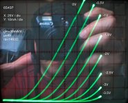
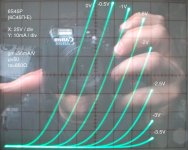
As a quick workaround I swapped the sensing resistor for a 1 ohm (1%) and used the vertical gain (i.e. lower scale) of the oscilloscope to compensate for the signal magnitude drop of x10. I was worried about the noise pickup, but still in a breadboard works a charm!
You can clearly see the impact in the 6C45 curves. Even the graphically calculated parameters are very different!
I will probably leave the 1 ohm resistor or add a switch to alternate between 10 and 1 ohm resistors.
Thanks for the feedback. I will read about the uTracer.
As a quick workaround I swapped the sensing resistor for a 1 ohm (1%) and used the vertical gain (i.e. lower scale) of the oscilloscope to compensate for the signal magnitude drop of x10. I was worried about the noise pickup, but still in a breadboard works a charm!
You can clearly see the impact in the 6C45 curves. Even the graphically calculated parameters are very different!
I will probably leave the 1 ohm resistor or add a switch to alternate between 10 and 1 ohm resistors.
Attachments
What options are available to minimise the measuring error introduced by the cathode sensing resistor for high gm tubes?
From Linear Tech application note 105:
Attachments
I have not had much time lately but finally I was able to do something.
I bolted and wired all transformers ( no picture yet ). I ended up adding an additional unregulated bias supply. This one goes to -350 and will be variable with a pot. I am copying the Tek 570 so I am able to compare dual tubes.
When one grid is being exited with the step signal, the other is biased very negative to ensure no conduction. A switch will toggle between the two grid signal sources and the grids.
Started populating the top plate. There are two generic binding posts with their corresponding pin jacks to add some flexibility. The right hand side has the test points for x,y and common.
Tomorrow I am building the socket adaptors. The templates are ready.
I bolted and wired all transformers ( no picture yet ). I ended up adding an additional unregulated bias supply. This one goes to -350 and will be variable with a pot. I am copying the Tek 570 so I am able to compare dual tubes.
When one grid is being exited with the step signal, the other is biased very negative to ensure no conduction. A switch will toggle between the two grid signal sources and the grids.
Started populating the top plate. There are two generic binding posts with their corresponding pin jacks to add some flexibility. The right hand side has the test points for x,y and common.
An externally hosted image should be here but it was not working when we last tested it.
Tomorrow I am building the socket adaptors. The templates are ready.
An externally hosted image should be here but it was not working when we last tested it.
What options are available to minimise the measuring error introduced by the cathode sensing resistor for high gm tubes?
I know is not easy to measure the current at the anode, it has been discussed around here before.
Was there a reason you didn't want to put the sensing resistor between the bridge rectifier and ground (and make P2 and R27 large to minimise their current demand)?
Hi Merlin,
Not sure if I understand the question. Surely P2 can be larger to minimise current. I had a 220K at hand, so used it Perhaps a 1meg pot would be better here?
R27 and R28 is just a x10 divider for the oscilloscope. I believe Michael Koster suggested a different way of measuring the anode current but I don't understand how.
Perhaps you can explain here and help me out?
Thanks
Ale
Attachments
For use in a tube tracer the current measuring circuit needs to work at low electrode voltages also.
hard to beat a floating power supply with low side sensing
It will work with very low voltages as well -- and you don't have to float the supply which has its own issues, and you can use very low sense resistors because of the high gain of the diff amp. You can use a pair and sense current in each direction, if, for instance you wanted to do bjt's, depletion MOSFETs etc.
Pretty good over a wide range if you ask me:
An externally hosted image should be here but it was not working when we last tested it.
I am paying attention to the current sensing conversation.
For now i am only sensing the current from the plate supply. I have a 10 ohm resistor (8 80 ohm .1% in parallel) from the common ground to the centertap of the plate transformer.
At some point i want to add a sensor on the stair step drive, so i can get current curves for the grid and screen (screen driven curves). The resistor rout doesn't currently work because there is always around 10ma being consumed at idle by the step amplifier. I would need to offset that to zero on the sensing device.
Alfredo
- Status
- This old topic is closed. If you want to reopen this topic, contact a moderator using the "Report Post" button.
- Home
- Design & Build
- Equipment & Tools
- DIY Curve Tracer