Hi Alfredo
Looking really good!! And the new scope as well!
I got another XY analogue oscilloscope for £30 as my old one sort of died.
Got the idea perfectly. I'm currently using a 1uF electrolytic cap. Will add the resistor, shouldn't be too difficult to hack the pcb for this.
I'm traveling at the moment so won't be able to do any work till I return in two weeks
Thanks for the help
PS: please post some of the new plots tomorrow!!
Cheers
Ale
6336A Triode curves
Finally a real power tube, a 6336a. It is supposed to be hard to drive. I had to put a series grid resistor of 500 ohms as without it some steps showed some oscillation.
The small variac that I am using to control the level of the HV drive (feeding a HV tranny Hammond 278cx) is running out of steam. I did not use any series resistor to limit the current on the HV drive.
The grid drive is the one from the previous post at 10V per step, so up to -150V.
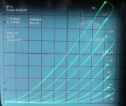
I need to get used to the Rigol XY display, not as clean as the analog scope. The capture below shows a more aggressive HV and some non lineal curves can be seen as I am pushing the small variac. Need to get a beefier one. The current sensing resistor is a 10 ohm 10% (1 watt) i had in my bin. Need to get better ones. So 250mv is 25ma.
Next step is to stuff the boards and pots into a box for a permanent setup. For now I think I am leaving the HV supply (with variac) as a separate component as it is heavy.
I may use a pair of LME49810 to make a hybrid 6336A SE amp.
Link to short video clip of analog scope curves
This one is also of an aggressive HV drive, stressing the variac.
Finally a real power tube, a 6336a. It is supposed to be hard to drive. I had to put a series grid resistor of 500 ohms as without it some steps showed some oscillation.
The small variac that I am using to control the level of the HV drive (feeding a HV tranny Hammond 278cx) is running out of steam. I did not use any series resistor to limit the current on the HV drive.
The grid drive is the one from the previous post at 10V per step, so up to -150V.
An externally hosted image should be here but it was not working when we last tested it.
I need to get used to the Rigol XY display, not as clean as the analog scope. The capture below shows a more aggressive HV and some non lineal curves can be seen as I am pushing the small variac. Need to get a beefier one. The current sensing resistor is a 10 ohm 10% (1 watt) i had in my bin. Need to get better ones. So 250mv is 25ma.
An externally hosted image should be here but it was not working when we last tested it.
Next step is to stuff the boards and pots into a box for a permanent setup. For now I think I am leaving the HV supply (with variac) as a separate component as it is heavy.
I may use a pair of LME49810 to make a hybrid 6336A SE amp.
Link to short video clip of analog scope curves
This one is also of an aggressive HV drive, stressing the variac.
Last edited:
Today I traced a GE 6L6GC. The variac can handle this tube. I also captured the xy data from the rigol using a USB stick and opened the .csv data in excel.
An externally hosted image should be here but it was not working when we last tested it.
An externally hosted image should be here but it was not working when we last tested it.
The software becomes more time consuming than the hardware.
Before you capture the data it's a good idea to do a little work on establishing a "settling" algorithm for your ADC. That is, determine the number of measurements at each point, establish a tolerance (per cent) at which you will include or exclude a data-point, and figure out whether to RMS the values, average them or use some other methodology to get the best fitting values. This way you eliminate a lot of the noise. When I did my tracer, the microprocessor didn't have anywhere near the speed to do this but it is much more readily realized today.
I think that you'll find one of the most valuable tools you can use your tracer for is comparing two devices, or the two halves of the same device (ecc83 etc.)
Hi Alfredo,
These look really good. Are you still working without a chassis? How do you manage the shielding of the A,G and K cables from your board to the valve socket?
Cheers,
Ale
Yes, still working without a chassis using 2 foot cables. Chassis will come this weekend. I am planning to use an old tube tester as the heater and socket platform.
Alfredo
Re: 200Hz/240Hz PLL stability
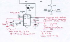
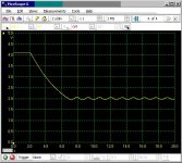
For a fast and stable PLL - lock in ~3s - I recommend something like this (pic 1). Series resistor from pin13-pin9 = 220K, shunt cap from pin9 replaced by 470nF, parallell with 68K+10u.
Hopefully I will be able to upload the pictures, they also show the measured lock transient (voltage on pin9) for the original and modified circuit.
The HC4046 is actually quite tricky to use, as the design equations in the data sheet are not accurate. A much better (and much less popular) part to use is the HCT9046A.
/tb
Attachments
Hi TB,
Thanks for the contribution. It seems quite a different setup for the HC4046.
Today I hacked my PCB to add 100K resistor in series with C9 (1uF) as per Alfredo's suggestion. It did improved locking significantly. However, I do have an issue now with the DC offset. It looks like the grid signal drifts a bit.
Do you recommend making the changes as you suggested earlier? May struggle to add all those additional caps and resistors, but can give it a go.
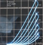
Attached are two new plots with a high gm triode (6N6P-I) and a very high gm (6Z51P) triode-strapped pentode. Both were a bit of a challenge and added a 1K resistor to the grid wire in addition to the ferrite bead I have around the cable.
Cheers,
Ale
Thanks for the contribution. It seems quite a different setup for the HC4046.
Today I hacked my PCB to add 100K resistor in series with C9 (1uF) as per Alfredo's suggestion. It did improved locking significantly. However, I do have an issue now with the DC offset. It looks like the grid signal drifts a bit.
Do you recommend making the changes as you suggested earlier? May struggle to add all those additional caps and resistors, but can give it a go.
Attached are two new plots with a high gm triode (6N6P-I) and a very high gm (6Z51P) triode-strapped pentode. Both were a bit of a challenge and added a 1K resistor to the grid wire in addition to the ferrite bead I have around the cable.
Cheers,
Ale
Attachments
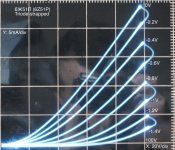
12BK5 Trioded Curves
Tested a 12BK5 in triode mode from a batch that I purchased for $1 each. The curve tracer is quite stable. Yesterday I did notice that what I thought was a weak variac ended up being a bad bridge rectifier. I went to a full wave rectifier using 1n4007 diodes and using the transformer center tap to ground. I hooked up the 6336A and now I did not have issues with supplying current.
For the 12BK5 i used a 3K series resistor with the plate drive. I added plate and screen dissipation for a 11.5 W PD curve. Rigol .csv export to excel.
An externally hosted image should be here but it was not working when we last tested it.
An externally hosted image should be here but it was not working when we last tested it.
You have an issue with the DC offset of the Clock? Is it constant? If it is constant the counter should not care. On my setup I do have a DC blocking cap before my grid driver, otherwise it screws up my negative bias control.
Is the grid signal that drifts now (up and down randomly and slowly). It can drift 0.5v or more. I need to measure the output of the counter to identify where does it start drifting....
Is the grid signal that drifts now (up and down randomly and slowly). It can drift 0.5v or more. I need to measure the output of the counter to identify where does it start drifting....
Not sure if i makes a difference. But on my 4520 counter I ended up placing a 100uf in parallel to the 100nf cap right at the VDD pin.
Alfredo
I hope you can get it to behave.
I took a quick video of the control of the steps per family using the LM339 comparator.
Video showing control of steps per family
I took a quick video of the control of the steps per family using the LM339 comparator.
Video showing control of steps per family
12BY7A trioded curves
100mv=10ma
An externally hosted image should be here but it was not working when we last tested it.
An externally hosted image should be here but it was not working when we last tested it.
100mv=10ma
6EB8 Triode Curves
Thanks Gootee, I requested the changes as you suggested.
I am reposting the pictures with the correct title on them. I noticed something, the curves are very similar (almost identical) to the 12By7A trioded curves
100mv=10ma
Thanks Gootee, I requested the changes as you suggested.
I am reposting the pictures with the correct title on them. I noticed something, the curves are very similar (almost identical) to the 12By7A trioded curves
An externally hosted image should be here but it was not working when we last tested it.
An externally hosted image should be here but it was not working when we last tested it.
100mv=10ma
Last edited:
25F5A trioded curves
100mv=10ma
An externally hosted image should be here but it was not working when we last tested it.
An externally hosted image should be here but it was not working when we last tested it.
100mv=10ma
Last edited:
Hi Alfredo,
They look really neat. Well done!
Attached is my latest test. 4P1L triode-strapped - one of my favourite tubes. It's really linear as you can see. Superb valve!
I managed to get a Beckman Industrial analogue oscilloscope in very good state for only £20 although it costed me more the train ticket to go and collect it
I suspect that the stability issue may be related to the regulation of the back to back transformers as it appears when I measuring a valve under large anode current. Need to investigate a bit.
Will add the decoupling electrolytic to the +5V rail and probably change the PLL components as suggested in previous posts.
Will report progress later
Attachments
- Status
- This old topic is closed. If you want to reopen this topic, contact a moderator using the "Report Post" button.
- Home
- Design & Build
- Equipment & Tools
- DIY Curve Tracer