Hello
I have a Pioneer SX-34 tube receiver.
I have recap some parts of the amp and put new output tubes, and the amp section work perfect and sound very good.
The AM tuner work good.
But the FM tuner don't work (except a small white noise), I've just test all the tuner tubes and they are fair to good.
I really don't see why the FM tuner don't work, (even using it with a good antenna).
Any hint ?
Here is the schematic;
AK Database PDF Gallery - Pioneer Receivers/Pioneer SX34 Schematic
Thank
Bye
gaetan
Last edited:
The schematic shows a lot of the bias conditions for the FM circuit. Check all the voltages and see if you can find one that is out from expected values.
If you have an exceptionally strong station in your area, tune to that approximate frequency based on the dial indicator and look to see if any of the bias voltages shift as you tune in that area.
If you have an exceptionally strong station in your area, tune to that approximate frequency based on the dial indicator and look to see if any of the bias voltages shift as you tune in that area.
Am, Fm radios, tv tuners and many other high frequency tuners generate a frequency higher/lower than the tuned frequency. Both of these frequencies, the tuned frequency of the radio station and the higher "local oscillator" frequency are mixed together in a non linear fashion in a device called a "mixer" to produce difference frequency. The mixer also produces a sum. These sum and differences are commonly called inter-modulation distortion when produced at audio frequencies. At RF frequencies the difference is what we want and is called the IF or intermediate frequency. It is always lower than the radio station frequency and is easier to amplify. In AM radios the IF is 455Khz, in FM it is 10.7 Mhz. If the local oscillator or mixer is not working you won't get any FM radio. Quite often the local oscillator and mixer is one tube. Another problem you may have but less likely is the AFC control. Automatic Frequency Control. The local oscillator drifts so a correction voltage from the FM decoder is sent to the oscillator to keep it stable. I am surprised that I don't see a switch to turn off the AFC. Normally you tune in a station, then turn on the afc to lock it in. If one of the IF stages is dead it is possible that you will hear nothing, but most likely you may hear a strong local station faintly. Did you try the FM selector(mono). The FM MPX selector requires that the FM stereo decoder is working.
Test all the tubes in the FM section first. Coupling caps could be bad (electrically leaky) shifting the bias as well.
Hello
I forgot to ask.
Which part numbers those coupling (bias) capacitors have in the schematic ?
Thank
Bye
Gaetan
If you have another FM receiver, tune the Pioneer to near the centre of the band. Then on the second receiver tune to 10.7MHz above and below the Pioneer (you will have to move the Pioneer tuning a little too). The aim is to see whether the local oscillator is working.
For example, Pioneer on 95MHz. Try other on 105.7MHz. Put Pioneer on 100MHz. Try other on 89.3MHz. You should hear a plain carrier on one of these positions, but not both.
Fixing an FM unit requires some knowledge and some RF test equipment, except for the simplest faults.
For example, Pioneer on 95MHz. Try other on 105.7MHz. Put Pioneer on 100MHz. Try other on 89.3MHz. You should hear a plain carrier on one of these positions, but not both.
Fixing an FM unit requires some knowledge and some RF test equipment, except for the simplest faults.
is there a signal strength meter / tuning indicator on the receiver? Does it change when you turn the tuning knob up/down?
Hello
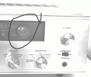
It's a green glowing tube signal strength meter / tuning indicator.
And nothing move when I turn the tuning knob up/down.
Thank
Bye
Gaetan
Attachments
Last edited:
For the beginning please touch grids (pin 1) of V9, V8, V7 by a screwdriver tip and tell if you hear some noise.
Hello
Wen I touch grids (pin 1) of V7, V8, V9 by a screwdriver tip;
V7 do a strong motor boat noise
V8 do a very faint noise
V9 do a very very faint noise
Thank
Bye
Gaetan
If you are getting noise on the IF grids when switched to FM then the problem is probably in the front-end.
What is the voltage on C42 (marked as 94V on diagram)? If it is significantly lower than this then the local oscillator has probably stopped.
Hello
I've just measure voltage across C42, it's reading 100v dc.
Thank
Bye
Gaetan
Thanks!
Now please try pins 8 and 2 of V301.
Also, when you rotate FM tuning knob, do rotors of capacitor VC301 moving?
Hello
The V301 tube are enclosed in a soldered metal case shielding and I can't access pins 8 and 2.
The rotors of capacitor VC301 are moving wen I rotate the FM tuning knob.
Here is some photos.
Thank
Bye
Gaetan
Attachments
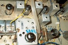
That metal case should have that VC301 inside: that variable capacitor to the left from it on the 1'st picture is for AM band. If the 1'st FM IF stage amplifies the signal well, something is wrong between it and that "soldered metal case". Please try to remove V301 tube to check if loudness of white noise changes without it. This thingy is FM preselector, radio frequency amplifier, heterodyne oscillator and mixer. The left part of the tube is RF amp stage, the right part is both oscillator and mixer. When you tune on different stations heterodyne tunes 10.7 MHz apart from selected station, so after the mixer you have always 10.7 MHz no matter which station you tune on. It is IF, Intermediate Frequency, so IF amplifier always amplifies and filters on the single IF. It is working: you tested it by screwdriver.
That metal case should have that VC301 inside: that variable capacitor to the left from it on the 1'st picture is for AM band. If the 1'st FM IF stage amplifies the signal well, something is wrong between it and that "soldered metal case". Please try to remove V301 tube to check if loudness of white noise changes without it. This thingy is FM preselector, radio frequency amplifier, heterodyne oscillator and mixer. The left part of the tube is RF amp stage, the right part is both oscillator and mixer. When you tune on different stations heterodyne tunes 10.7 MHz apart from selected station, so after the mixer you have always 10.7 MHz no matter which station you tune on. It is IF, Intermediate Frequency, so IF amplifier always amplifies and filters on the single IF. It is working: you tested it by screwdriver.
Hello
I have take out V301, and the loudness of white noise seem a bit higher.
Since you did said that VC301 are inside the metal box, I've take out the V301 tube, and I can see now VC301.
The rotors of the variable capacitor VC301 are moving wen I rotate the FM tuning knob, so the rotor shaft of VC301 are not broken.
Thank you
Bye
Gaetan
Last edited:
the first half of the tube 6AQ8 is the RF amplifier. It is a wide band amplifier and it is not input tuned. The output is tuned. Attach if you can a long insulated wire to pin6. This is now your input to the tuned circuit. Any different? while you are trouble shooting check if you can the diodes D2 and D3, these are crucial to detecting the audio signal from the FM, also C60 the 5uf 25 volt cap.. Audio output comes from the junction of C52 C53 and ground
the first half of the tube 6AQ8 is the RF amplifier. It is a wide band amplifier and it is not input tuned. The output is tuned. Attach if you can a long insulated wire to pin6. This is now your input to the tuned circuit. Any different? while you are trouble shooting check if you can the diodes D2 and D3, these are crucial to detecting the audio signal from the FM, also C60 the 5uf 25 volt cap.. Audio output comes from the junction of C52 C53 and ground
Hello
I have to go out of town for few days, I will do thoses tests wen I will be back.
Thank you
Bye
Gaetan
- Status
- This old topic is closed. If you want to reopen this topic, contact a moderator using the "Report Post" button.
- Home
- Amplifiers
- Tubes / Valves
- A problem with a tube receiver