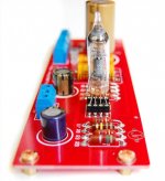

The picture basically shows you the schematic. The 6111 is a dual triode so the parts hidden behind the tube are a mirror of whats in front. The very back looks like part of the heater supply. Look at the resistor bands for the values, once you have them its easy to figure out where they go. The capacitor values may not be be visible but again they aren't hard to calculate.
It has only one tube, so it's very easy to understand about its' schematic.
Possible to post it? Thanks!
schematic
An externally hosted image should be here but it was not working when we last tested it.
Possible to post it? Thanks!
- Status
- This old topic is closed. If you want to reopen this topic, contact a moderator using the "Report Post" button.
- Home
- Amplifiers
- Tubes / Valves
- GE6111 Preamplifier