Hmmm... 0.9A emitter current could require as much as 20mA base current.
May have to rethink if this can be done in a single BJT? Darlington no prob.
I wonder if modulation of filament temperature can affect quiescent current
in the way I am hoping, or temperature only sets an upper limit for emission?
May have to rethink if this can be done in a single BJT? Darlington no prob.
I wonder if modulation of filament temperature can affect quiescent current
in the way I am hoping, or temperature only sets an upper limit for emission?
I won't debate that there is a huge time constant, but would have
to prove over 120 degrees phase shift and loop gain over unity.
We just need to make sure that R3 C2 corners far from the
same frequency as the filament time constant. So gain is down
before we have to deal with more than 90 degree phase shift.
Same concept as "Sluggin the dominant pole", er whatever...
I don't know the time constant of the filament, I don't think it is
anywhere near the same length as a full warmup. R3 C2 corners
at 4Hz as drawn, so we hope filament gotta be slower than that?
We could probably get away with 100uF and corner at 20Hz.
I'm not counting cathode impedance or base leakage into my RC
calculation. It might not be as low as 4Hz like I'm thinking. This
transistor really needs upgrade to Darlington or Sziklai for reason
of insufficient beta (20mA base current as drawn). Impedance of
Darlingon base would increase sufficiently to put it out the RC,
cathode impedance might still be a factor of some significance.
or temperature only sets an upper limit for emission?
Almost.
Does this make any sense, or just a new way to kill a tube?
The words that springs to mind is "Why ?". At startup you're going to subject the heater to the better part of 12V and multiply thermal shock to it as if its low R at room temperature wasn't enough of a cause for concern, and when it warms the cathode up it just might oscillate, as you have already pointed out.
Why not opt for separate CCS heater supply instead ?
Reason I had thrown the 1ohm at it, 12A max.
Valid point. Deserves much safer current limit...
Why? Throw 8 mismatched 6L6 at an AB amp
and know all plates are biased just under 30W
at all times and conditions. Even as tubes age.
Run filament colder when new, hotter when old.
My first theory was auto minimum idle bias for
smooth AB crossing. Then later realize just run
plates exactly hot as they are rated at all times
probably crosses no worse.
It will auto itself to class A if AB isn't needed.
Could auto itself to class B, if stressed? Maybe
emission limit already prevents that situation?
----
What I worry most: Filament may only cap the
maximum emission, little or no effect 60mA idle?
Just have to try it and see... I havn't found any
good paper on what really happens.
Last edited:
3.4A max inrush assuming dead short filament.
4mA max base current assuming worst beta.
There has to be a simple way to limit inrush
down to an amp-point-two-er-so? Thenagin'
a filament isn't a dead short even when cold.
Well, it ain't suppsed to be anywho. Where'd
my darn multimeter go? If I knew that, prolly
wouldn't know where I stashed my Pentodes.
Still wasting my time if only an emission cap.
Need to resolve that truth or fictionage first.
Attachments
Last edited:
Since you have such a tricky feedback by current with 2 long time constants you can get better result more directly: CCS in cathode shunted by a capacitor that gives the same time constant without stability concerns.
However, if you want to prolong tube's life increasing emission when it ages, you still can add such a through-filament feedback, but sensing cathode voltage instead of voltage drop on a resistor.
However, if you want to prolong tube's life increasing emission when it ages, you still can add such a through-filament feedback, but sensing cathode voltage instead of voltage drop on a resistor.
This was sensing 11.3 minus cathode voltage...
And why did I need a CCS again? Could garter
across pairs if I cared the transformer balances...
But if emission variables like age and temperature
only have measurable effects at full saturation,
this bias scheme might not properly sense for it.
How much does ideal fixed bias differ from new
6L6GC to same tube when almost worn out?
Now another question... Is RMS plate dissipation
estimatable at a bypassed cathode resistor? The
plate isn't sitting at 450V when the signal swings.
Voltage swings down as Current swings up, versa.
Average drop at bypass not true plate RMS math.
Whats the simplest bias that holds a true 30WRMS
on the plate at all times? Do I need an IR sensor or
thermistor to watchdog over the darn plate?
Last edited:
This was sensing 11.3 minus cathode voltage...
...that means, you were sensing cathode current.
And why did I need a CCS again?
In order to control cathode temperature depending on bias voltage needed for the current set by a CCS.
I like the idea to measure IR radiation. It is exactly proportional to plate dissipation.
")
However, I prefer my old good method: to sense screen grid current. It is more practical.
Last edited:
How does screen grid current method work?
Like a charm!
Sharp compression instead of clipping.
Input attenuator is formed by a resistor and light controlled resistor; LED senses current of screen grids such a way it starts flashing when output stage approaches clipping (sharp rise of screen grid current).
All except still not RMS of plate.
You still can use IR sensor to control CCS...
Last edited:
Screen optoisolator useful in its own way. But I don't
see how it gives information that could be abused to
regulate the filament and extend life of the cathode.
G1 leakage currents in AB2 might tell us something
useful about the emission health of the cathode...
But prolly have to run screen voltage so low that
G1 leaks a little, even at quiescence.
Crank the filament up till G1 leaks some prerequisite
amount? If G1 is driven positive by cathode, source,
or emitter: otoisolator above plate, drain, or collector
of that drive device should be well out the audio path?
Last edited:
Like a charm!
Sharp compression instead of clipping.
Input attenuator is formed by a resistor and light controlled resistor; LED senses current of screen grids such a way it starts flashing when output stage approaches clipping (sharp rise of screen grid current).
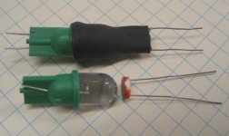
That's an interesting approach I'll have to try. I already have a setup I've been working on for a LA-2A style leveling amplifier using an LED+LDR instead of the T4B with the flourescent panel.
I found a blue-green LED of the best wavelength for the CdS photoresistor (LDR) and used hot melt-heatshrink to make an assembly. I also made one with a more common bright green LED that worked about as well, so no need for the special color LED I guess...
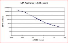
I characterized resistance vs. current of the device and found a nearly perfect log-log characteristic.
Also of interest is that the LDR responds slowly, minimizing needs for filtering of the audio signal driving it, and it responds more quickly to brighter light. It also has a slow turn-off which is slower after exposure to a brighter light. All characteristics that define the unique natural smoothness of the LA-2A.
Attachments
So that's what this is for.Reason I had thrown the 1ohm at it, 12A max.
Valid point. Deserves much safer current limit...
Why? Throw 8 mismatched 6L6 at an AB amp
and know all plates are biased just under 30W
at all times and conditions. Even as tubes age.
Run filament colder when new, hotter when old.
I was guessing the circuit was designed to make a tube warm up faster by dumping a lot more than rated power (and quite possibly higher than rated filament voltage! Not even a transformer filament winding does that) into the filament at turn-on. Once it warms up and the designed-for quiestent current is flowing through the cathode, filament power drops to normal.
There has to be a much better way to do what you want to do, one that limits the power into the filament to no more than, say, 10 or 20 percent over the rated power.
First thing I'd do is make an emissions curve vs. filament power (actual measured voltage x actual measured current) for several "new" and "old" tubes, from that one can have a good idea of what's possible and reasonable.
Nah, I'd still want to limit cold current so it warms up slowly.
3-4A isn't unusual for cold 6L6 filament anyway, so anything
less than 3A is most likely slower than usual warmup.
The only other time the filament should be running above 0.9A
rating would be when the cathode is old and worn out, perhaps
with an LED that warns of this condition?
I would hope a new cathode that doesn't even need full rated
heater power could be run cooler than spec, and last longer...
If we can persuade junk box tubes of different age to match
emissions, thats really the sorta thing what I was after.
-----
1.2A absolute current limit and transistor shunt that away as
normal emission levels are detected. Might be an approach...
Last edited:
- Status
- This old topic is closed. If you want to reopen this topic, contact a moderator using the "Report Post" button.
- Home
- Amplifiers
- Tubes / Valves
- Filament Autobias