Ok. C7 is to be deleted,(it produces something like a chaos), the primary winding capacitance, among other OT parameters, need to be redefined by measuring the actual thing. Under the 6J7's K, there will be a Vishay TTLR4400 low current red led.
Besides, if there is success replacing R1-C2 with a generous string of LEDs, à la SY, I will call it "the Roxanne's amplifier"
Besides, if there is success replacing R1-C2 with a generous string of LEDs, à la SY, I will call it "the Roxanne's amplifier"
Attachments
Last edited:

One thought I have would be to replace R15 (39 ohm) with three 120 ohm resistors - one in series with each of the diode strings to promote current sharing between the strings of LEDs. From an AC standpoint this will look exactly the same to the 6V6 cathode and assure reasonably good current sharing with unmatched LEDs.
Are there no ill effects with the long string of LEDs?
I'm curious, why use the 6sj7 in the first stage? At the moment I'm investigating a prototype using 6gk5 in the first stage, and 6v6 in the output, which seems to work ok enough. Clean sound, but not a lot of power, asking for efficient speakers and a small room.
I'm curious, why use the 6sj7 in the first stage? At the moment I'm investigating a prototype using 6gk5 in the first stage, and 6v6 in the output, which seems to work ok enough. Clean sound, but not a lot of power, asking for efficient speakers and a small room.
6J7G is the desired tube, but there is no LTSpice model out there, AFAIK. It is
said to be superior to the 6SJ7. Plus, is one really cool looking top
cap tube. ((thinK about how two of these plus two 6V6G's and a 5u4G
rectifier will look like on top of the chassis)
SY "Red Light District" , demonstrates that the led string approach
is quite feasible...
It avoid the Lytics as well as the fixed bias
Maybe this will help you. It's a model from this data sheet, triode connected:
http://www.scottbecker.net/tube/sheets/084/6/6J7G.pdf
* 6j7g-ra LTSpice model
.subckt 6j7g-ra P G K
CPG P G 1.8p
CGK G K 2.6p
CPK P K 17p
* koren4 model
Bp P K I=(0.0149067781m)*uramp(V(P,K)*ln(1.0+exp((9.208278358)+(9.208278358)*(20.88749615)*V(G,K)/V(P,K)))/(9.208278358))**(1.367679703)
.ends 6j7g-ra
Thanks ikoflexer, I'll keep the model for anoter project ,maybe.
This one is in a bit "ideologic" spirit of a pure pentode mixed feedback 5W SE.
Take a look to the Kevin Kennedy thread about his pentode-pentode 6V6, and you will see what fine results can be achieved out of this combo.
Cheers
J
This one is in a bit "ideologic" spirit of a pure pentode mixed feedback 5W SE.
Take a look to the Kevin Kennedy thread about his pentode-pentode 6V6, and you will see what fine results can be achieved out of this combo.
Cheers
J
Last edited:
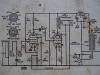
FYIY, here's a schematic of a headphone amp that I made for a friend, using SE output transformers from a Wollensak tape recorder, and parts from my junkbox. I used a TubeCad software to determine the component values, and checked everything manually with tube curves, rulers, etc.
There isn't any global feedback. It sound pretty good as is, although there is a slight amount of hum with sensitive headphones, and if I had to do it over, I would have used DC on the filaments.
There isn't any global feedback. It sound pretty good as is, although there is a slight amount of hum with sensitive headphones, and if I had to do it over, I would have used DC on the filaments.
Attachments
- Status
- This old topic is closed. If you want to reopen this topic, contact a moderator using the "Report Post" button.
- Home
- Amplifiers
- Tubes / Valves
- 6v6 SEP