I thought there was an update to the Bill amplifier using a CCS to replace R12.
In any case, that may be an easy modification that will solve most of the issues you may have in the ECC99 stage.
You might enjoy TubeCad software for modeling these circuits. Just remember that modeling software finds "by the book" operating points, not the "sweet spot".
In any case, that may be an easy modification that will solve most of the issues you may have in the ECC99 stage.
You might enjoy TubeCad software for modeling these circuits. Just remember that modeling software finds "by the book" operating points, not the "sweet spot".
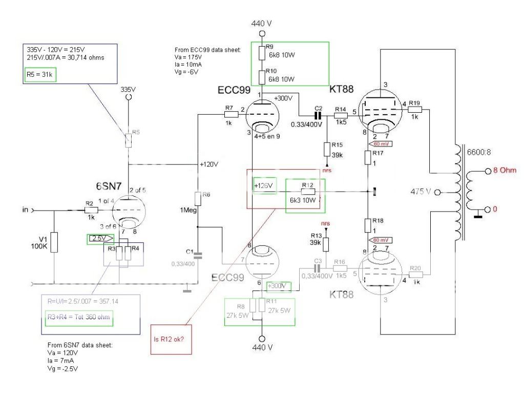
You have 130V available in the cathode circuit. How about a current source instead of R12?
FWIW, Triode Dick's Mono Bill has a CCS on the cathodes in place of R12......
Triode Dick's Page (link is a little strange...click projects, then Mono Bill)
A 10M45S would be another CCS solution.
Last edited:
13mA for the pair of ECC99 gives 6.5mA per tube.
top anode is at 440-(.0065*30000)=245V
A-K = 245-130 = 115V
Bottom anode is at 440-(0.0065*37170)=198.4
A-K = 198.4-130 = 68.39V
I believe the lower ECC99 will start saturating before you drive the KT88 fully and you will get high distortion.
I would lower the current through the pair by increasing R12, or change the anode resistor values to give less drop, or both. Depends on how the ECC99s are best operated.
I would have to look up the ECC99 and KT88 specs to give more detail.
JJ Electronic ECC99 data sheet
JJ Electronic KT88 data sheet
I know from playing around with 5687 and 7119 (USA types similar to ECC99) that these sound thin and weedy with only 6.5mA going through them. They begin to "turn on" at about 10 or 11 mA. I like them with at least that.
Looking at the JJ curves, it seems an ECC99 with 6.5mA through it is operating in the "knee" of the curves. That would indicate higher internal anode resistance, higher distortion, etc. That might be the source of "thin" sound right there. I think the ECC99 would perform better with more current going through it, not less. But that would require a total re-design of the circuit...
Why not try bypassing the cathode resistor of the 6SN7 as it is now, with a capacitor of about 330uF 16V. Any high quality electrolytic caps from 270uF to 470uF should work; whatever you have around (but not physically large, high voltage types). That would take away the negative feedback from cathode degeneration and maybe change the tone of that stage to your liking (higher gain, maybe more full-sounding). Easy enough to try, right?
--
thats what it says here too..... What Is Biasing?
actually strange, because TriodeDick's first KT88 PP from 2001 had cathode bypass caps, on KT88
and the later 3 versions have none
is it cost saving ?
Attachments
Thanks all ")
So, my picture is right around the 6SN7? Then i will change my resistors..
And to get more mA in the ECC99 i change the anode- resistor to 20K and cathode resistor to 24,6K..right? That will bias the ECC99 to more like 10mA?
I have looked at a CCS.. Didn't understand **** And i have a seperate PSU and no free pins in my connector...
MANY thanks! //Daniel
So, my picture is right around the 6SN7? Then i will change my resistors..
And to get more mA in the ECC99 i change the anode- resistor to 20K and cathode resistor to 24,6K..right? That will bias the ECC99 to more like 10mA?
I have looked at a CCS.. Didn't understand ****
And i have a seperate PSU and no free pins in my connector...MANY thanks! //Daniel
So, my picture is right around the 6SN7? Then i will change my resistors..
Reducing the anode load resistor value to 27k will raise the harmonic distortion in that first stage. You generally want the anode load resistor value to be 4x or more the internal anode resistance of the tube. 6SN7 internal resistance is 8k ohms or so, so you'd normally want more like 33k or 36k as the anode load. But try the 27k, see what it sounds like. It might be good...
And to get more mA in the ECC99 i change the anode- resistor to 20K and cathode resistor to 24,6K..right? That will bias the ECC99 to more like 10mA?
20k resistor with ECC99 at 10mA would drop 200V.
24.6k resistor with 20mA across it would drop 492V!! That can't be right (and that won't work).
That ECC99 stage is trickier to figure.
We need 130V at the joined cathodes of the ECC99's, right? So 130/.02 = 6500. You want ECC99 cathode resistor to be 6500 ohms (two 13k in parallel would work).
In order to get 10mA through each ECC99 half, we want the anode voltage to be about 175V.
175V (anode) + 130V (cathode) = 300V.
That means the anode resistor needs to drop 140V from the Ebb of +440V. With 10mA going through it, the anode resistor will need to be 14k. That would work!
From the JJ data sheet, the bias for the ECC99 at that point should be -6V.
You will probably need to adjust the values of the 6SN7 anode resistor and the ECC99 cathode resistor to get the right relationship of voltages between the two. You need to get the anode voltage of the 6SN7 to be 6V lower than the 130V at the ECC99 cathodes. So the anode voltage of the 6SN7 needs to be +124V.
Now the question is, will -6V bias on the ECC99's allow enough voltage swing to drive the KT88's to full power?
--
Last edited:
OK, maybe this editing of your schematic will explain better....
Please note that I'm not suggesting that this is any kind of an optimal design idea. I'd change things around were it my amp. But I hope this helps get the idea across better.
--
Forgot to mention:
Notice how the +120V anode voltage of the 6SN7 goes directly to the ECC99 grids? The ECC99 grids are at +120V.
Now look at the ECC99 cathodes. They're at +126V. That puts the ECC99 grid 6 volts lower than the ECC99 cathodes. That creates the -6V grid bias for the ECC99 triodes.
The ECC99 triodes each have 10mA going through them.
The 6k3 resistor from the ECC99 cathodes to ground has 20mA going through it (10mA from each of the two ECC99 triodes). 6300 ohms * .02 ampere = 126V.
One more thing:
I'd definitely try bypassing the cathode resistor of the 6SN7 with a 330uF capacitor. Choose a high quality, low ESR electrolytic. You don't need anything more than a 6.3V rated part. A 16V part would work fine too. 63V would be complete overkill, and too physically large.
--
Last edited:
. Electro Harmonix sounded like ...
how long did you let this tube run in circuit?
and,
was it new?
Last edited:
actually strange, because TriodeDick's first KT88 PP from 2001 had cathode bypass caps, on KT88
and the later 3 versions have none
is it cost saving ?
I think he switched it to fixed bias, but it's not very clear from the schematic.
--
Hi"
tomtt: I run the tube for around 2 hours. And it wasn't new, i had it in a old el34 amp for maybe 300 hours.
rongon: I think i have started to understand it at last In the old design there was around 205 v at the ecc99 pin 1 and 6. In your design there will be 300 v. That's correct? Better?
And the optimal resistor value at R5 is above 33K..will 31 K be alright?
Thanks //Daniel
tomtt: I run the tube for around 2 hours. And it wasn't new, i had it in a old el34 amp for maybe 300 hours.
rongon: I think i have started to understand it at last
In the old design there was around 205 v at the ecc99 pin 1 and 6. In your design there will be 300 v. That's correct? Better?And the optimal resistor value at R5 is above 33K..will 31 K be alright?
Thanks //Daniel
Hi"
rongon: I think i have started to understand it at last
I think it *might* sound better. Not because it's a higher voltage or anything like that. I tried to find a "better" operating point for the 6SN7 and then find a matching operating point for the ECC99 that follows. (The 6SN7 anode being DC-coupled to the ECC99 grids makes this more complicated than if the two stages were RC-coupled.)
However, now that I know that the ECC99 had 205V on its anodes, I can see that the ECC99 was biased kind of "cold," which could sound a bit "dry."
ECC99 with 205V at the anode and 130V at the cathode, and a B+ of 440V with anode load resistor of 30k ohms:
Va = 75V
Ia = 8mA
Vg = -10V
I'm sorry, that just does not compute. There's no way the ECC99 would bias up like that. There must be some mistake. I checked this against the ECC99 characteristic curves from the JJ Electronic ECC99 data sheet. I'm pretty sure I'm doing this right...
As I wrote earlier, I've built some stuff using 5687, which is very similar to ECC99 but with a different pinout. My experience is that the 5687 sounds thin and a touch "harsh" at currents lower than 10mA, and the original schematic you posted had the ECC99 biased to have much less current going through each of its two triodes. I suspect that that might sound thin and/or "dry." Since that was your complaint about the sound of your amp, I thought it might be fun to try to fix that...
With the current set at about 10mA per ECC99 triode, the ECC99 should have an internal resistance of about 3.5k ohms. That means an anode load resistor of 13k to 15k ohms would be desirable (3500 * 4 = 14,000). I found 13.5k ohms would work in this circuit, and that's within the desirable range (and happens to equal two 27k ohm resistors in parallel).
And the optimal resistor value at R5 is above 33K..will 31 K be alright?
31k ohms for the 6SN7 anode load is close enough to 33k that it should be fine. (8,000 * 4 = 32,000)
--
Choosing operating points along the tube's characteristic curves is where a lot of the fun of designing an amplifier lies -- or at least for me, at this point.
After experimenting with various triodes in a simple single-stage line amp (common cathode), I've heard for myself that the relationship between the triode's internal anode resistance and the value of anode load resistor is important to the sound you get out of that tube -- just like it says in the books. You really do want the anode load resistor to be at least four times the resistance value of the triode's internal resistance.
However, a triode's internal resistance will increase if you run it at a lower than optimal current. If you do that, you'll need to increase the value of the anode load resistor to compensate. However, a triode run at low current also changes in other ways -- its amplification factor (mu) may be a little lower, and its transconductance goes down (sometimes a lot).
I've found that there is a 'sweet spot' for each triode, a point at which the tube begins to get fully 'turned on.' Really low current operating points tend (to my ears at least) to yield anemic or "dry" sound, and that's what your complaint was. So I tried to address it by suggesting that you put a touch more current through your driver stage tubes.
I'm not an expert -- I'm a complete amateur at this -- but I've been trying to learn as best I can. I hope someone who knows more than I do will weigh in and correct any mistakes I've made.
--
Another thing...
Since you don't have a bypass capacitor in parallel with the 6SN7 cathode resistor, the 6SN7's internal anode resistance will be higher. How to figure that out:
From Designing Common-Cathode Amplifiers
Rk' = (Rp+ra)/(mu+1)
for 6SN7 with 31k anode load and unbypassed 360 ohm cathode resistor:
the resistance seen looking into the plate when the cathode resistor is unbypassed is:
ra'(unbypassed Rk) = ra + (mu + 1)*Rk
8000 + (20 + 1) * 360 = 15,560
That means the ra of the 6SN7 is now about 15k ohms. You'll need a 60k ohm anode load resistor to meet the 4 * ra rule for the anode load resistor. I think you need to try bypassing the cathode of the 6SN7 with a 330uF 16v capacitor (low ESR electrolytic), at least to hear if that improves the sound for you. If you don't like the sound with the cathode bypass capacitor, then leave it off.
--
Hi!
Ok, think i have it now. I will send for parts and change it when they arrive.
Is it nesesary to have so large resistor 6,8 K / 10W at the anode? Will 5 W work?
Thanks
Ok, think i have it now. I will send for parts and change it when they arrive.
An externally hosted image should be here but it was not working when we last tested it.
Is it nesesary to have so large resistor 6,8 K / 10W at the anode? Will 5 W work?
Thanks
You might want to think about the gain structure. If you're committed to not having a feedback loop from the transformer secondary to the cathode of the first stage tube (as usually done in a 5-20 circuit like this), and putting aside the distortion and source impedance performance, you'll have an amp with VERY high gain. Eyeballing it, you'll have something like 16-17 from the first stage, maybe 8-9 from the second. So at clipping, the input voltage is something like 300mV. Normal input sensitivities are 5-7 times that. That means that your preamp will almost always be running well under unity gain, and its noise performance will be 5-7 times worse than with a more conventional gain structure.
This can all be handled in system design, but if you have a preamp with gain (most common), you'll be blown out of the room with the volume control barely cracked open.
This can all be handled in system design, but if you have a preamp with gain (most common), you'll be blown out of the room with the volume control barely cracked open.
Yes, i have consider that. Since i have a preamp maybe i should ad a NFB.. Will i have to change something else? Or could i just ad a resistor and a small cap? What value? 15K and 180pF maybe..
From what I've seen, there are two ways to go about this.
1) Add NFB to reduce gain (and reduce harmonic distortion).
2) Take a stage away (the 6SN7 input stage).
Option 1) is the more common, and would probably be the more desirable, especially with your UL-wired KT88 output stage.
I tried option 2) in a triode power amp and found that it works for me. I figured the first voltage amplifier stage (your 1/2 6SN7 first stage) is an unnecessary duplication of the line stage amp. So why not get rid of the power amp's first stage?
I can think of one reason. Putting the phase splitter/driver all in one stage would not perform as well as a two-stage driver where the first stage does the phase splitting and the second does the driving of the output stage. But ignoring that...
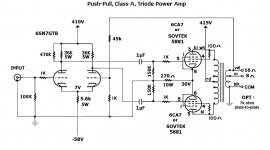
Here's a two-stage EL34 (6CA7) power amp I made on a Dyna ST70 chassis, as an experiment. It turned out better than I expected. It's not optimal at all, but maybe somebody would like to comment on it?
Attachments
Last edited:
6sn7 variables
A while back I sold about 40 6sn7 tubes of many makes
It turned into a interesting adventure as I had buyers, one who just left his programing job in the middle of the day, desparate to get versions of 6sny tubes I thought were lousy!
I prefer the GE gray plates as smooth and lush, and I kept those....
But there have been many versions of tubes made, and the guys with the expensive gear know what version of most common tubes gives them the sound they want.
The 6sn7 has to have enough idle to become "Lush" and have a deep sound stage. Cathode "R"s of around 330 to 510 ohms and plate values of around
33K work great.
It is not that easy to do some math and dertime values, real sonic tests should always do that, as tubes can be pretty sneaky
Local smal amounts of plate to grid feedback, a 2.2meg "R: from plate to grid on a 6sn7 will shape up that square wave, make the tube quiet.
Also, if the cathode is bypassed, put about 51 to 120 ohms from cathode to cap so some dry "R" for neg feedback
Also could be the resistors, I always uded 2-watt carbons for the Vintage sound, so remember, caps and "R"s have thier sonics
Building line stages and other gear with vintage tubes showed in sonic tests that a lot of tubes like round number values. 330K grid, 330 ohm kathode, and 33k plate sound and work well.
The SRPP stage can be dry and flat, so you have to decide on "Tone" or "Clean" when picking desings.
I prefer the classic stages as more "Tone" of the Vintage style
Another trick that Marantz and other great designers used was to have a small value "R" in series with the grid "R" to ground, and at that junction, add a small amount of + volts to push the idle up for a more lush sound.
I was re-building a Marantz preamp, noticed the grid "R"s were two "R"s in series with the junction point going to the power supply???
so what he was doing was to add about 3-5V + to the grids of the 12ax7s so they would idle high for more Lush.
Adjusting the voltage to the driver is important, as 6sn7s have a lot of current gain and do not need to run too hot, 300+ more that enough, and when you go over about 275+ the tube gets more harsh and "Hot" sound
- Status
- This old topic is closed. If you want to reopen this topic, contact a moderator using the "Report Post" button.
- Home
- Amplifiers
- Tubes / Valves
- Sound of the 6SN7?