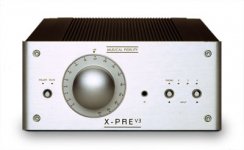
Im in the process of modifying my MF X-PRE,
so far ive replaced all the capacitors and i need help for the next part.
Firstly, im not sure if there would be any definate improvement replacing the quad opamp, and if i can find the specs of it or it i can afford it.
Im also considering replacing all the diodes.
What i want to know is if anyone has this amp and has modified it, or is any good at finding out specifications for componants.
I need to find out what type of diode to get, there are 2 massive ones and I have no idea what to replace them with (aparently it makes a big difference though)
I will upload some pictures of the componants im unsure about and i would really appreciate it if someone could give me a hand identifying them 🙂
Im in the process of modifying my MF X-PRE,
so far ive replaced all the capacitors and i need help for the next part.
Firstly, im not sure if there would be any definate improvement replacing the quad opamp, and if i can find the specs of it or it i can afford it.
Im also considering replacing all the diodes.
How about replacing all the resistors first ?
What you might think about is "what is the goal" and "how do I measure my progress towards that goal". A goal of making the Pre sound as good as it can be is reasonable, but wholesale replacement of parts is very unlikely to get you there. Try substituting whole sections of your system. This is much more likely to product quantatative changes that you can hear, and help descover how to get the most bang for your buck.
If we are going to lend helpfull advice we really need to know more about the entire system. Good Luck - Yea pics
If we are going to lend helpfull advice we really need to know more about the entire system. Good Luck - Yea pics
Thanks for everyones help, i apologise for not uploading the pics in time.
To arnulf, ive established that for any difference in resistors i would have to go for audiophile standard carbon composite ones which for the improvement they would give, are a little out of my price range 😛
and firecheif, thats the upgraded model. mines a little older than that:
http://is.gumtree.com/image/extrabig/17236840.jpg
il upload the pics in my next post in a sec
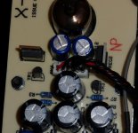
here are the pics of my amp.


Right. These 3 photos are taken during and after the modification. I’m going to go into more detail of what I did and plan to do so everyone has more of an idea of what I need help with.
I've replaced most major caps (all apart from a couple which haven't arrived in the post yet). This HAS made a noticeable difference. It will hopefully make a bigger difference when I get to replace the last few. I used the same capacitance with a higher voltage and a better brand name so hopefully better build. I also stuck to the same types of capacitors e.g. film caps or electrolytic.
Now I’ve been advised that as well as replacing caps, replacing the rectifier will make a good difference. This is where my first problem starts. In the circuit there are 6 small diodes and 4 triacs. One diode is for the LED and one is near the power source. That leaves 4 that are close and near a bunch of filters so I’m assuming this is the rectifier. I’m not entirely sure if I should replace the triacs, and what specs to use on them. Or if that will actually make a difference. so right now the plan for me is to order the 5 diodes (I’m not bothering with the LED one) and wait for some well educated genius to tell me what triode to get 😀
All help is much appreciated guys 🙂
You wouldn't happen to have schematic of this thing handy for us, would you ? It would show where those components are located so it would be easier to point out how they affect the output. I'm most curious about those 4 triacs you mentioned ... 2 I'd undertand (one per channel for a crappy chopper PSU) but four ?
http://www.diyaudio.com/forums/atta...musical-fidelity-x-pre-mf_x10d-schematics.gif
http://img.photobucket.com/albums/v221/kepa1/MF_X10DPSSchematics.gif
though these are actually the schematics for the x10, im 99% sure its the same circuitry inside.
if you can make any sense of this that would be great 🙂
http://img.photobucket.com/albums/v221/kepa1/MF_X10DPSSchematics.gif
though these are actually the schematics for the x10, im 99% sure its the same circuitry inside.
if you can make any sense of this that would be great 🙂
Those are transistors, each pair constitutes a constant current source according to your schematic.
The bigger TO-220 thingies aren't shown in the schematic but print on the board implies that they are linear voltage regulators (probably one for each rail).
The bigger TO-220 thingies aren't shown in the schematic but print on the board implies that they are linear voltage regulators (probably one for each rail).
Maybe I'm wrong, but C1 and C5 in the psu should be opposite polarity, isn't it?
Sajti
- Status
- Not open for further replies.
- Home
- Amplifiers
- Tubes / Valves
- X-PRE musical fidelity preamp. need help modifying