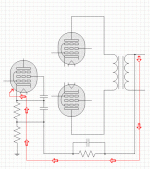
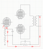
Here is a generic amplifier schematic with the output stage and input stage, but the rest of the circuit left out, just to show the signal path for global negative feedback. The question is whether or not the connection through the capacitor to the screen grid is a necessary component to the feedback.
Attachments
You have current mode feedback into the lower cathode resistor of the leftmost tube.
The cap to the screen is not necessary, and will provide additional feedback, however you need a voltage source to bias the screen in addition to the capacitor. I believe this will be voltage negative feedback as drawn, presuming the current mode feedback is negative.
The cap to the screen is not necessary, and will provide additional feedback, however you need a voltage source to bias the screen in addition to the capacitor. I believe this will be voltage negative feedback as drawn, presuming the current mode feedback is negative.
The cap to the screen grid is not part of the feedback loop, but ensures that the screen grid is decoupled to the cathode. This is necessary for normal pentode operation.
The situation you have drawn is voltage series negative feedback. This is because it is sampling the output voltage, and applying a fraction of this in series with the input voltage. The result, apart from reduction in gain and distortion, is a lowering of output impedance and a raising of input impedance.
BTW are you making progress in your quest to understand valve amplifiers?
The result, apart from reduction in gain and distortion, is a lowering of output impedance and a raising of input impedance.
Does NFB not lower the input impedance too?
Yes, I am making progress. I have several books and some help from a few tube amp manufacturers. I have redrawn the global feedback diagram without the connection to the grid, because it is not part of the feedback loop, and I want to keep it as simple as possible.
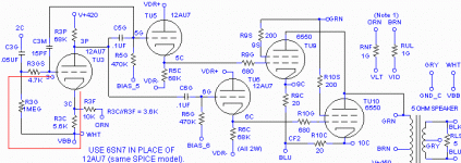
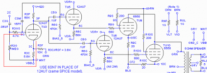
Another issue is local negative feedback. I have attached part of a schematic with a red line outlining the loop. Is this correct, and which direction does the feedback current flow, towards the grid or towards the cathode?
This schematic is from Norman Koren's The Emperor's New Amplifier (Copyright Norman Koren):
The Emperor's New Amplifier
Attachments
Last edited:
I have attached part of a schematic with a red line outlining the loop. Is this correct, and which direction does the feedback current flow, towards the grid or towards the cathode?
Neither, the feedback is caused between the anode and the cathode and is independent of the grid.
I.e. when the tube conducts, the cathode voltage rises, closing the voltage gap between grid and cathode which turns the tube off slightly - lowering conduction.
The extension of this principle is the phase splitter.
When applied in shunt, not series as here.Does NFB not lower the input impedance too?
Neither. There is a feedback voltage applied to the cathode, which is in series with the input. This raises input impedance. The feedback voltage arises from sampling the output current via the cathode resistor, so it raises output impedance too.and which direction does the feedback current flow, towards the grid or towards the cathode?
Feedback can sense either voltage or current at the output, and can apply either a voltage in series or a current in parallel ("shunt") at the input. Sometimes a combination is used. However, the most common form in valve circuits is voltage sensing applied in series. The effect for solid-state devices is exactly the same, so if you understand feedback for one type of active device then you can directly apply it any other type.
The next thing I need to do is draw global and local negative feedback using solid state devices. I'll need some help there.
Here is a picture I drew for students long time ago...

So, I still have the question. Regardless of what other parts of the amplifier circuit are involved, does the circuit outlined in red in the Norman Koren circuit represent local feedback?
Yes, and you may find the answer on the picture I posted for you in my previous message.
So, I still have the question. Regardless of what other parts of the amplifier circuit are involved, does the circuit outlined in red in the Norman Koren circuit represent local feedback?
No I don't think so as local feedback does not have to touch the grid.
The same current that flows through the tube flows through the cathode bias resistor as well. It creates a voltage drop on this resistor that is proportional to current and it's resistance. This voltage drop is effectively in series with the path of input signal that comes to the grid in respect to cathode, i.e. input signal minus viltage drop on the cathode bias resistor is applied between cathode and control grid.
If R3F (10K) is left open-circuit as shown then yes this is local feedback. However, R3F looks like it is intended as a place to inject some global feedback too.
There is also local feedback via C3M (15pF). So this stage has two local negative feedback loops, which to some extent work in opposite directions.
There is also local feedback via C3M (15pF). So this stage has two local negative feedback loops, which to some extent work in opposite directions.
The question is whether or not the connection through the capacitor to the screen grid is a necessary component to the feedback.
Bypassing the screen to the cathode is not a part of the NFB shown here. However, it is still necessary. The voltage that counts is the voltage referenced to the cathode, not to ground. When applying that NFB signal to the cathode, the screen grid has to move with it in order to maintain a constant Vsgk. If Vsgk is not constant, then your pentode isn't operating as a pentode (it's a form of ultralinear then). Any time you have the possibility of AC on the cathode, then you need to bypass the screen to the cathode and not ground.
Sdinfo, all current flows in loops. Where is the current coming from that flows through the feedback resistors? The output is floating, the only signal you will get is through the insulation of the transformer. Unless I'm missing something obvious?
Wouldn't you need to reference the non-feedback lead of the output transformer to ground?
- keantoken
Wouldn't you need to reference the non-feedback lead of the output transformer to ground?
- keantoken
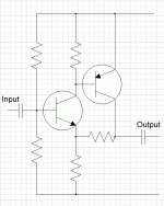
To Wavebourn - Here is a diagram of the one you showed in the bottom right corner of your diagram. Do I have the input and output connections labeled correctly? And, should there be a ground connection on the bottom horizontal path?
Attachments
To Wavebourn - Here is a diagram of the one you showed in the bottom right corner of your diagram. Do I have the input and output connections labeled correctly? And, should there be a ground connection on the bottom horizontal path?
Yes.
- Status
- This old topic is closed. If you want to reopen this topic, contact a moderator using the "Report Post" button.
- Home
- Amplifiers
- Tubes / Valves
- global negative feedback schematic
