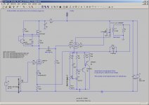
This is the initial stab at a schematic for the "No Light District" push-pull amplifier inspired by SY's "Red Light District" amp and by my own cantankerous/contrarian nature. The inspiration was a conversation with SY at the first Burning Amp get-together regarding the RLD and active bias schemes to replace the LED array. As usual, it takes time for things to brew.
The circuit shown has a differential front end rather than the triode front end/concertina phase splitter used in the RLD in order to allow partial feedback experiments. A setup similar to Stu's would probably work ok as well, as the 6CW5 does not appear to be an exceptionally difficult beast to drive. The Pete Millett front end with differential pentodes would also work, so his "red board" could be used as a basis for experiments. I chose the 6CW5 outputs in order to properly use a batch of Baldwin organ transformers scored on E-pay. They were set up to work with 6L6 outputs, and have a 6K impedance working into a 16 ohm speaker. Used with an 8 ohm speaker, they will be just right for the 6CW5s and a lower B+ voltage.
The bias network I chose is a bit complex, but has all the bells and whistles to get rid of all the little peaks and flurbles I saw in my simulation experiments with simpler circuits. Seeing as the 6CW5 doesn't require an exceptionally high bias voltage, I may try an alternate TL431/Darlington active circuit that has a lower parts count. I will post that as time allows, as I want to do one more simulation regarding a possible enhancement.
At any rate, the circuit is a first hack at what I want to try, and will no doubt evolve a bit. All the ugly bits can easily go on on a hunk of perf board squirreled away under the chassis. I may use a roasting pan for the chassis. Ikea and Target have some possible candidates. The Ikea pans are especially cheap, and are made of stainless steel. The natural finish might look pretty cool, especially if brushed.
Attachments
An RC damping network with said film capacitor may be more appropriate. That worked well on the active bias circuit used with my "Mighty Mite" amp. I'll check my simulations when I get to work tomorrow.
Yes, it turns out that I did have an RC damper across the shunt regulator in my simulation at work. Somewhere around a few tents of a microfarad to a microfarad with 1 to 10 ohms in series does the trick. It's difficult to really predict what exactly will be needed to do the job, as the fuzz that it suppressing is very small in amplitude (much, much less that the gross voltage change due to the load step), and may not exist at all in a real circuit doe to the limited slew rate of the tube stage and the undocumented parasistic capacitances that exist in a real circuit. If you want to start with something, then 1uF and 2.2 ohms in series would be ok.
On another note, attached is a circuit using a TL431 that is a bit simpler. A cascode transistor protects the TL431, so it can be used in a situation where the required bias voltage is higher than the 35V maximum rated voltage of the TL431. I may start with this circuit to see if it works as well as simulation suggests.
On another note, attached is a circuit using a TL431 that is a bit simpler. A cascode transistor protects the TL431, so it can be used in a situation where the required bias voltage is higher than the 35V maximum rated voltage of the TL431. I may start with this circuit to see if it works as well as simulation suggests.
Attachments
I did some comparison distortion testing with a similar voltage sink, buffered LED Bias and standard (bypassed) cathode bias with my Firefly 6P1P amp and found that the voltage sink gave twice the distortion of cathode bias. I did not test a LED array for comparison, but wish I had. This results may be particular to the 6P1P and other similar small tetrodes.
Has anyone else actually built a circuit and tested it?
I think this was the version I tested with, except I ended up removing hthe 33uF cap.
Has anyone else actually built a circuit and tested it?
I think this was the version I tested with, except I ended up removing hthe 33uF cap.
Attachments
Last edited:
Should there be a resistor (or break) between the +250 on the left side and the +265 on the right? I don't like feeding the driver B+ directly from the output stage B+ without some isolation.
I don't understand why you felt compelled to sling a 33uF feedforward cap into your design. Also, since you are looking at a single-ended design, you'll need some keep-alive bias to keep the circuit from drying out and cutting off during the negative 1/2 cycle. An approprately sized resistor from B+ will work in a pinch. I would also feel more comfortable with some realistically sized PNPs as the pass elements. I don't think you can even get 2N3638s any more, except maybe someone's ancient parts stash.
Last edited:
I'm only running 35mA bias current so the 3638As are fine. I do have a stash, but they are virtually the same as a 2N3904 (IIRC) and very similar to 2N2907. You could also stick 2N2222As in there and it wouldn't make much difference.
The 33uF FF cap was an experiment that proved to be pretty much useless. I was trying to use FF to eliminate some voltage variation.
I never saw problems with cutoff, but I was more interested in small signal distortion and found it to be unacceptable. This may be due to the SE amp I'm working with, the particulars of my circuit or a general characteristic of Voltage Sink operation.
Just thought I'd point out my measured results and was wondering if anyone else had actually built a circuit and tested it yet.
I use a hefty pass transistor, as one also has to plan for the instance when the amp is driven hard. Silicon is cheap - toasted tubes and output XFMRs aren't.(Think like George...)
Anyway, attached is the next pass of the NLD with the promised TL431 bias regulator circuit. If I'm lucky, I'll get one of these done in time for Burning Amp 2010. To pile heresy on top of heresy, it'll use an SMPS, as it's the simplest way for me to get the voltages I want in the space I want.
Anyway, attached is the next pass of the NLD with the promised TL431 bias regulator circuit. If I'm lucky, I'll get one of these done in time for Burning Amp 2010. To pile heresy on top of heresy, it'll use an SMPS, as it's the simplest way for me to get the voltages I want in the space I want.
Attachments
I perhaps spoke too soon. The NLD may still use an SMPS, but I'm also trying out one of the power transformers from the Musical Power Supplies folks (actually, I think it's just one folk). I have one piece each of the PT275-2 and PT 325-2, and I'm going to try each with a choke input filter to see if they'll make the grade for a 6CW5-based amplifier. Using both filament windings in 6.3V mode, there's enough power to light up the 6CW5s and the 12AU7s. The bias tap will also come in handy for generating the required negative bias for the input LTP tail current sink. The price wasn't bad, either.
The 275V Musical Power Supplies transformer gave me only ~195V with a 6mH choke input filter and 150 ma load (choke's too lossy, transformer also has some drop). I will try the 325V transformer for form's sake with a smaller and less lossy choke, but I'll probably end up with an SMPS for this amp, too (the board is 90% stuffed, need to wind the transformer). When you've done SMPS for 30+ years, they're sort of a knee-jerk reflex, especially if you've worked out the application-specific problems for tube amps with a few previous builds.
Last edited:
This a rough-up of another possibility for the NLD if I give up the option of messing around with partial feedback. I drill the same number of tube socket holes in the chassis as in the case of the diff-amp first stage option, but the clutter is less below decks. The value for the source resistor for current source load Q1 is a dummy until I test some devices to find the proper resistor for 5-6 ma plate current. I could get around this by doing a ring-of-two current source with a bipolar transistor and a HV P-channel mosfet (Fairchild makes some, and I have them).
If anyone has messed around with a solid state phase splitter, let me know, but I don't see any reason why it can't be done, and the mosfet will operate with a lot less voltage headroom than a tube without drying out prematurely. Again, the Supertex depletion mode fet is not necessary. One of the small N-channel HV enhancement mode fets could be used (Fairchild again makes a likely candidate). In that case, I would need to substitute a zener for the plain diode currently serving as gate clamp.
I was thinking of carting the chassis down to the basement tonight to start drilling some holes. A suitable SMPS is already built up and awaiting its first power-up. Interesting times lie ahead, but then, they always do...
For those of you thinking of a similar approach, substitute your own favorite hi-mu, low Rp RF triode for front end duty. The 6AM4 has a bunch of dedicated grid pins. Is is kosher to drive just one with a stopper resistor, or necessary to drive all the pins in parallel, each with its own stopper?
Attachments
Is is kosher to drive just one with a stopper resistor, or necessary to drive all the pins in parallel, each with its own stopper?
There are those who insist on a seperate resistor for each pin. I do not subscribe to that theory, and the Tubelab SE drives the 5842 through one stopper resistor. I use PC board construction ans simple leave the other pins unconnected. The 5842 is known for oscillation.
Thanks - there's nothing like experience. I'm happy to finally find a use for the 6AM4. It has a high mu (85) and lowish Rp (~8.5k) this is with a 10ma plate current, but it won't be too bad at 5-6 ma, either.
There are those who insist on a seperate resistor for each pin. I do not subscribe to that theory, and the Tubelab SE drives the 5842 through one stopper resistor. I use PC board construction ans simple leave the other pins unconnected. The 5842 is known for oscillation.
I have been asking this myself as well, but now I have two expert opinions towards the use of a single grid stopper. The other expert is EC8010
Something else: I have seen 'voltage controlled current sources' to feed DH cathodes, and it made me think about possibilities to make 'current controlled voltage sources', in that the circuit holds the current constant by varying voltage.
I notice that you have the B+ to the OPT coming from the right at 265V, but the trace continues to the left to the phase splitter and input gain stage, then off to the left where it is labled 250V.
Should there be a resistor in the series connection some where? Or, are they meant to be separate supplies?
Should there be a resistor in the series connection some where? Or, are they meant to be separate supplies?
Aha! - someone who actually looks at the schematic. My mistake, they were meant to be separate supplies, and there will be need to be a dropper resistor, as my SMPS is already built, and it only has the +265V output.
Last edited:
Is Q5 configured as a common base amplifier for voltage gain?
This is a good bit different than the variant I tested with.
This is a good bit different than the variant I tested with.
Q5 is a cascode transistor for the TL431, allowing its use at voltages greater than its 35V rating. This is not a concern for the 6CW5, but will be needed with nasty low-mu triodes that require a lightning bolt to bias them. They'll also need a Darlington with >100V capability, so a discrete Darlington is probably the way to go. The cascode also increases the high frequency impedance of the 431 and cleans up the output transient response in simulation. It'll be interesting so see if that benefit is also there for the real-world circuit.
- Status
- Not open for further replies.
- Home
- Amplifiers
- Tubes / Valves
- "No Light District" P-P amplifier