This. Plus it is always a gamble as crowd might just be gullible enough to fall for a silly idea and staunchly support it without any scientific reason behind it (I hate to bring up mr. Pass and his one transistor series of exercises once again ...). Dictionary says "staunchly" is a real word, much to my surprise.
Hi, Arnulf.
It seems that you are the most clever here....
Is this to say you are using the lamps to balance the current from the GM70 through the Output Transformer, so that you can use a non-gapped transformer and prevent saturation under normal bias condition?
Yes it is.
Hi.
About competence: I am an electronic engineer, not a DIYer... And you...?
Awesome diversion from schematic discussed
") Would you then care to explain these anyhow (in reference to the new schematic you posted today):
Would you then care to explain these anyhow (in reference to the new schematic you posted today):1: What is the impedance of a lightbulb running off 500V and how would it compare to (A) choke the size of the light bulb supply transformer and (B) output transformer the size of both lightbulb supply + existing OPT combined ?
2: Why would a circlotron require a coupling capacitor ? (you mentioned yours doesn't so this must be something unorthodox, a circlotron without one)
3: You mentioned this design saves some money. How much (in relative figures, I understand you wouldn't want to reveal absolute numbers) more does a choke cost compared to the price of the entire lightbulb section, including its transformer, filtering and other bits ?
4: I believe you mentioned output power, 29W if I'm not mistaken. What is the efficiency of your design and how would it fare compared to an amplifier with a true reactive load (efficiency-wise) ? An easy one for the engineer among us
And back to the original schematic, the one that was posted on the first page of this thread (resistive-load capacitor-coupled parafeed):
5: Same as question #3, what is the price ratio of 1 KV supply versus only 500V supply and a decent choke ? Since you're building 500V supplies for other amplifiers this should be an easy one for you to answer (just in relative figures, we wouldn't want you to divulge your business secrets
).6: Those "mF", are these really millifarads ? I mean an electronic engineer is surely familiar with the notation so these can't possibly be μF, yet I'm puzzled by your remark about bringing the costs down (albeit in a different creation of yours). What is the cut-off frequency of 4.7 millifard combined with multiple kiloohms anyway ? I'm not an electronic engineer but I'm sure you've got the figure handy somewhere, afterall you made the choice to put it there. I find it surprising that a production cost-minded person would go far in ensuring response almost down to DC, specially since I doubt the parafeed ttransformer is capable of performing its job that far down.
7: How linear a resistor is a lightbulb ? (this one refers to the excerpt Michael posted on page 2, I take you're the author)
8: How does tube dissipate half the power when running at the same operating point (Vq, Iq) when being loaded with a lightbulb instead of an OPT (at half the supply voltage, obviously, since comparison would be invalid if it wasn't made at same output power) ?
Hi, Arnulf.
It seems that you are the most clever here....
Looks like you manage to sneak this one-liner in while I was typing my message, again without addressing concerns posted so far. Neat
I realize it's late in Moscow now so I'm looking forward to your reply that doesn't consist merely of ad hominem attacks in the morning
Hi.
About competence: I am an electronic engineer, not a DIYer... And you...?
It seems to me, he is both. I saw a lot of graduates who were not DIYers. They were absolutely weak as engineers. But every DIYer I met as a student in TIASUR, both students and professors, were brilliant engineers and scientists as well.
I am both a DIYer and have a PhD in electronic engineering, as well as a BSc degree in physics. Having worked for many years in industry, I found that some professionals know less about their job than I know about my hobby.
We were commenting on the circuit diagram and blurb which was placed in front of us, which appeared to come from your website. If these are not descriptions of your products, then of course to that extent our comments do not apply.
We were commenting on the circuit diagram and blurb which was placed in front of us, which appeared to come from your website. If these are not descriptions of your products, then of course to that extent our comments do not apply.
A 25W/240V bulb will consume approximately 105mA at 240V, two in series with a 500V supply would represent about a 5K load.. This is actually an interestingly clever design - you might want to do a little analysis before you criticize further - as a cost saving approach it is certainly original.
The reference to saving a coupling capacitor is in reference to the typical parafeed which this most definitely is NOT. (Since there is no dc current through the transformer no gap is required.)
This is an interesting design, and it is a shame that the schematic and product description do not mention this interesting design twist. (And the fact that it is a variant on a circlotron should have been disclosed on eBay.) I am not sure that a resistor would not have served just as well, but 100W power resistors (I derate to 50% of power rating in my designs minimum) are a lot more expensive than a pair of 25W bulbs..
I am not sure of the exact output power capability, but the designer can confirm that..
Last edited:
Yes, it reminds a cyclotron, since output is connected to diagonals of the bridge. Speaking of a coupling cap, both PS-es have filter caps, so it is not a feature at all.
A bulb as you know is non-linear device: the lower is frequency the higher is it's DR. And it's resistance depends on the voltage in outlet. And so is tube's internal resistance! They change in opposite direction with voltage in outlet.
Last fall I wanted to make a fun-workshop on BAF building a hybrid amp out of one vacuum triode and MOSFET follower loaded by a light-bulb. I don't know who passed telepathic waves, but Nelson Pass as I heard did something similar...
Yes, it reminds a cyclotron, since output is connected to diagonals of the bridge. Speaking of a coupling cap, both PS-es have filter caps, so it is not a feature at all.
A bulb as you know is non-linear device: the lower is frequency the higher is it's DR. And it's resistance depends on the voltage in outlet. And so is tube's internal resistance! They change in opposite direction with voltage in outlet.
Last fall I wanted to make a fun-workshop on BAF building a hybrid amp out of one vacuum triode and MOSFET follower loaded by a light-bulb. I don't know who passed telepathic waves, but Nelson Pass as I heard did something similar...
Light bulb loading goes back at least 10yrs... I saw it for the first time around the end of 2001.. So someone lost to time gets the credit for the original idea..
Light bulb loading goes back at least 10yrs...
Much more. It was used in vacuum tube sinewave oscillators to stabilize amplitude. I can't edit my previous message: I was typing slower than thinking, should be written as "the higher is it's DR non-linearity".
Last edited:
Much more. It was used in vacuum tube sinewave oscillators to stabilize amplitude. I can't edit my previous message: I was typing slower than thinking, should be written as "the higher is it's DR non-linearity".
Actually I was aware of its use as an amplitude stabilizing component in Weinbridge oscillators all the way back to the original HP oscillator in the early 1930s, but I was basically referring to its use in the output stage of a tube amplifier.
Last edited:
All I had to say I already said.
Who knows what we are talking about, will understand perfectly by the schematic I posted (included the meaning of "mF").
To Kevinkr: the output power is 29 Watts if the output stage is correctly driven. As you know in a circlotron the tubes (the tube in this case) are cathode followers. It means that the stage does not have voltage gain. So, the output signal will have the same amplitude of the driving one, a part the "current" gain of the cathode follower it self. The advantage is that this output signal will have a very low impedence compared with a plate output and will be able to drive aprimary winding much more "short" .
Actually the output transformer has a transformation ratio of 18.3. So, if a power of 29 Watts on 8 Ohm means 15 Volts RMS out of the secondary winding, on the primary it will be required 300 Volts RNS from the output stage. It's not so difficult to have 300 Volts from a driver stage with a voltage supply of 500 and 500 Volts on the plate of GM70 are more than enough for to pass out 300 Volts from this tube in cathode follower operation. With a transformation ratio of 18,3, the primary winding will have an impedence of 2700 Ohm.
The power supply does not need so much a LC filter, because with the circlotron operation you will have two ripple in phase opposition as well as for the normal push pull stage.
Best regards, Ciro.
Using a non-linear resistor as a cathode load will do much less harm than using it as an anode load (provided the valve is really acting as a cathode follower - this depends on how the grid is driven), but it is still non-linear - not "linear" as claimed in the blurb. A low wattage bulb such as 25W will have a thinner filament so will have a shorter thermal time constant than a more powerful bulb. It will react to low frequencies. Advantages are that it is cheap, and behaves a bit like a CCS.
By the way, why do people draw a circlotron with crossed over lines? It seems to hide the fact that this is just a cathode follower with a centre-tapped PSU. Is a single-ended circlotron really a circlotron at all?
By the way, why do people draw a circlotron with crossed over lines? It seems to hide the fact that this is just a cathode follower with a centre-tapped PSU. Is a single-ended circlotron really a circlotron at all?
Certainly the Vetruvio GM70SET is a great value per money, and have hard wiring, unlike others famous big triode amps I seen that use PCB circuit board and are priced over tens of thousands dollards, and have to hide the inside of the amp in magazine tests.
I would like to thank Mr.Ciro for taking time to post in this thread. I apologize for any inconvenience that this thread may have caused.
Best regards, Gustavo
I would like to thank Mr.Ciro for taking time to post in this thread. I apologize for any inconvenience that this thread may have caused.
Best regards, Gustavo
 I've pulled several posts. Confine your arguments to technical ones, not personal.
The power supply does not need so much a LC filter, because with the circlotron operation you will have two ripple in phase opposition as well as for the normal push pull stage.
Best regards, Ciro.
...which is a big mistake: it helps to silence hum in pauses, but causes intermodulations between signal and ripples.
Since ripple has high order harmonics, won't they also be present and not rejected by the amp output stage?
Yes, but in pauses they are hidden, that creates an impression of clean power.
Hi, there.
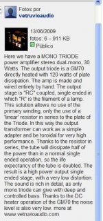
I am "Mr Vetruvio" or, if you prefere, Ciro Cravetto from Italy. The disigner of this amp.
1) There is written nowhere that the schematic visible on my site is the same there is inside the amp.
2)Here you can find the very basic schematic of the amp actually for sale. The amp is a circlotron in S.E.: the bulb on the other side works as a constant current generator and allows to achieve a perfect output offset without any continuous current in the primary winding of the the output transformer. It means that there's no need of any output capacitor.
...
Good luck, Ciro Cravetto
Hello Ciro,
Thanks for joining this discussion and bearing with us.
Please excuse my earlier sarcasm, and understand that on face value your claims in the attached ebay listing do not hang together. Is a light bulb any more linear than a simple resistor? Or maybe you mean to say that it holds constant current, which is clearly not the same as linearity.
On what do you base the claim that the output stage is power efficient (uses less power) when it has a current balancing load that needs to dissipate as much power as the output tube? How does adding an extra load increase the plate efficiency of the triode? But then, that's not your claim, only the implication... Double the life expectancy? Class A 30W output requires a certain plate dissipation +/- only 10 or 20%, no way to reduce it by 1/2!
Also, note in your description you state that the output is SE and RC coupled with the light bulb in series with the plate of the triode (I summarize). This to me describes the free schematic of the SE GM70 posted on your website more closely than the schematic you posted above. Why do you call it RC coupled series SE in your ebay ad and then tell us it's a circlotron with no output capacitor? That at least is cause for some question.
Other issues may be related to translation to English; you probably meant to say that the OPT primary winding doesn't need to pass the DC operating current for the GM70, not that it isn't used at all.
--------------------
By the way, I see no problem with something crafted in someone's garage. What if no one had bought any model 200 oscillators because Bill Hewlett built them in a garage on Addison Avenue?
I think the spam cans are kinda utilitarian cool
Attachments
Last edited:
- Status
- This old topic is closed. If you want to reopen this topic, contact a moderator using the "Report Post" button.
- Home
- Amplifiers
- Tubes / Valves
- The Impressive Vetruvio GM70 SET amp.