There used to be (mid 70's) a consumer version that plugged into the tape loop on many receivers or in between the preamp and the amp on a component system. A local HiFi Associates store had one on display. It did make some albums (CD's weren't invented yet) sound better. I had a friend who had one for a while and said that after about a year he couldn't stand listening to it anymore.
That fad also started in the 70's with radio stations that wanted to be louder than the other guy so they compressed the life out of the music and then cranked up the gain to increase the average modulation index. You couldn't make disco sound any worse! Record producers did the same. Carver came out with a box that attempted to undo the damage, the dynamic range expander and the peak unlimiter. There was another box called the auto correlator that attempted to filter out the hiss and pops from vinyl and tape. I have a Phase Linear 4000 preamp that has all of that stuff rolled up into one expensive box. After a few years, I too couldn't stand to listen to it anymore.
I have read some recent research that deals with the effects of listening on the brain. The human brain is a processing engine. It has a finite number of "MIPS" like a computer. Listening to music, speach or anything else uses some of the brain's MIPS. Listening to "damaged" sound uses up more MIPS than listening to perfect sound. This contributes to listener fatigue. This is why listen to a crappy PA system gives you a headache.
One study was attempting to correlate cell phone use with "distracted driving" auto acidents. The study used electro encephlagraphy to measure brain use and found that poor voice quality required considerably more MIPS to understand the conversation. It seems that the method of transmission (CDMA, GSM, etc), the bit rate, and the vocoder in use strongly correlate with the degree of distraction.
crushing the life out music is called the Waves L2 Sonic Maximizer
That fad also started in the 70's with radio stations that wanted to be louder than the other guy so they compressed the life out of the music and then cranked up the gain to increase the average modulation index. You couldn't make disco sound any worse! Record producers did the same. Carver came out with a box that attempted to undo the damage, the dynamic range expander and the peak unlimiter. There was another box called the auto correlator that attempted to filter out the hiss and pops from vinyl and tape. I have a Phase Linear 4000 preamp that has all of that stuff rolled up into one expensive box. After a few years, I too couldn't stand to listen to it anymore.
I have read some recent research that deals with the effects of listening on the brain. The human brain is a processing engine. It has a finite number of "MIPS" like a computer. Listening to music, speach or anything else uses some of the brain's MIPS. Listening to "damaged" sound uses up more MIPS than listening to perfect sound. This contributes to listener fatigue. This is why listen to a crappy PA system gives you a headache.
One study was attempting to correlate cell phone use with "distracted driving" auto acidents. The study used electro encephlagraphy to measure brain use and found that poor voice quality required considerably more MIPS to understand the conversation. It seems that the method of transmission (CDMA, GSM, etc), the bit rate, and the vocoder in use strongly correlate with the degree of distraction.
Meyer is actually top of the line
Really?

On the last AES convention in San Francisco, where they presented a huge phased array sound weapon, I approached a fullrange speaker and knocked it. I heard "Boom", like a bell... I looked at a lady and a gentlemen wearing nice strict suites, but they did not pay attention. I ringed again looking in the eyes of the gentlemen, but he looked as if he understood nothing, he did not know what means if speaker enclosure details ring!
"For Whom The Grill Talls?"
Later I was asked to help to one amateur chorus with sound amplification in one theater. She was crying aloud! She said guys in the theater are not professionals, she said they tortured her and children, she said they are bad, bad, bad people, she said they hate her and children, she said please do anything you can to help...
I brought my equipment consisting of foldable line arrays, vacuum tube power amp (actually, Vyramid-V-M currently), Behringer 31 band EQ, and my large diaphragm condensers.
I put everything on a stage, but when still connecting them a local guy (a nice guy, actually, and very knowledgeable as an audio engineer) suggested me to give him line level outputs so he could connect to his amps and "it will be louder". I answered, "No, it won't be louder". I knocked all around his JBL speakers, heard ringing on different frequencies, but he did not understand until I connected everything and made a frequency response flat. Children could sing on 3 feet distance from microphones, with no feedback, and 75 dB all over the theater... They were singing like without speakers, but louder. The teacher said that I am a magician... Later, thinking that I am still the magician, she asked me to edit the live record made from mixer's output.
However, I had to say that our magic science can't do that yet, despite Einstein & Lobachevsky suggested that the time is reversible... Today's "Top of the line" means top of that line where people stay in a queue for money they get from offering of those goods that are better advertised.
In the world of loud PA, Meyer is at the top of the pile. The top is shared by other companies as well - it called "parity product." But Meyer does find its way into many "high class" venues, such as operas. The CQ boxes are rather good.
Don't know what you were knocking on, but every Meyer cab I had the chance to thump has been amazingly dead. I'd love to be able to buy the same plywood they do. I'm not a Meyer fanboy, but the stuff works and works well. It would be my first choice.
I do understand about your adventures with the choir. Most soundmen just don't get it. They are used to mixing overblown rock, and don't understand anything else. I used to love getting a latin or jazz band on stage, I could actually make it sound good.
Back in the 80s in Paris, I tried to build a "hi-fi" PA rig for the jazz combos I was touring with. I ended up with Jean Hiraga's Altec A5s as my main rig. Amps were solid state or tube, whatever was handy. It sounded wonderful. Sorry I was not able to continue with that.
I got out of Audio and into video projection because I felt I was part of the problem that I hate so much, amplified sound.
OK back on topic. Will you be ale to show us some FFT of what your circuit does? That would be fun.
Don't know what you were knocking on, but every Meyer cab I had the chance to thump has been amazingly dead. I'd love to be able to buy the same plywood they do. I'm not a Meyer fanboy, but the stuff works and works well. It would be my first choice.
It was a grill, actually. Ringing like a bell. I know they do now very good DSP stuff (as I heard from my friend, real software genius, who works for them).
OK back on topic. Will you be ale to show us some FFT of what your circuit does? That would be fun.
No, I don't use simulations. But I can tell you, that the fun is in dynamics. When signal level is low it is quite clean, when it goes higher the specter goes wider, starting from the 2'nd harmonic. When signal decays it goes backwards: higher harmonics decay faster.
PS: I designed for rock bands in 70'th and 80'th. Custom things. It is totally different story. Ringing was not a problem, when it rings on certain frequencies highlighting fundamentals and belcanto formants. I did not fight against resonances, I was tuning them, so voiceless bass guitarist when screaming sounded almost like a professional singer. Later, I met hem, and he said something like, "We were recording on a studio recently. Man, they can't record my clean voice without distortions!"
Cool. I wasn't thinking of sims but measurements. Someone will have some soon. Better yet, I ought to build one of my own. =)
I will experiment with it later, probably it will end up with something slightly different. Like, a cathode follower between tubes, different types of tubes, optical attenuator instead of a pot, etc...
It is just an idea, I posted it for fun. I used it long time ago in a guitar pedal as a volume control, but with SS devices. JFET worked with zero D-S DC.
Artificial Hangover In Audio Circuits
http://www.fileden.com/files/2008/8/24/2063601/electronics/Hangover-p60.jpg
http://www.fileden.com/files/2008/8/24/2063601/electronics/Hangover-p61.jpg
http://www.fileden.com/files/2008/8/24/2063601/electronics/Hangover-p103.jpg
http://www.fileden.com/files/2008/8/24/2063601/electronics/Hangover-p104.jpg
http://www.fileden.com/files/2008/8/24/2063601/electronics/Hangover-p106.jpg
-----------------------------------------------
Old guys?? "Frequency translator" re: Big Star, Pink Floyd backgrounds - Page 2 - Gearslutz.com
currantbun
Hi folks, thanks for your interest, are you all mostly in the USA? Pleased to meet you all, I am in the UK. Before I joined EMI in London in 1969 I worked as a development engineer in radio communication systems and the frequency translator borrowed from that experience. It took about 6 months or so to design and build during quiet times often late into the night whilst being on call within the studios as an engineer providing technical support to studio sessions. I negotiated a total budget of GBP 100 with the studio manager, plus my time. That was the total cost. The device used thermionic valve (tube) technology, I remember that around 10 thermionic valves were used in the final device. As far as I am aware no photographs exist of the device and it had fallen into disuse and disrepair by 1975 which is the year I left the studios. It worked like this. It shifted the audio spectrum in a linear fashion, not harmonic. eg 1000Hz becomes 1010Hz, 2000Hz becomes 2010Hz, 3000Hz becomes 3010Hz etc. The audio baseband signal modulated a 10.7MHz carrier producing a resultant double sideband amplitude modulated radio signal. The carrier and one sideband were then filtered out producing a 10.7 MHz single sideband (SSB) radio signal with suppressed carrier. And this is where the fun starts. You then re-introduce the carrier at a slightly different frequency and demodulate the resulting signal producing a reconstituted audio passband that now has the necessary linear shift. If the re-inserted carrier is itself modulated at very low frequencies then the shift itself becomes variable and a multitude of various weird sounds can be produced. Feeding the output back to the input enabled even more possibilities and the device was exploited very effectively by AP on DSOTM. It was used on a number of other albums and continued in use as long as I was available to maintain it. It survived for quite a reasonable time in a very busy studio operation especially considering that it was constructed in prototype fashion on an unprotected open aluminium chassis with no case. At first the project had no name at all and was simply referred to as "my" project (the Keith Adkins project) but it was named as the Frequency Translator on completion. Any other questions I'll do my best to answer, hope this helps.
If you can find a communications receiver (not everyone will have one!!) and receive an SSB voice transmission you will be listening to the original audio after the modulation and filtering processes mentioned above, plus of course any effects created by the radio propagation. Most communications receivers will have a control called a BFO (beat frequency oscillator). I believe some CB radios that are SSB capable will also have this control, and it may be called a "clarifier". Adjust this control and you will be making a small adjustment to the re-inserted carrier mentioned above. This mis-tuning will give you the linear frequency translation effect, admittedly over a small passband, typically 300Hz to 3KHz. My original thought was what would happen if you created the same effect deliberately using the full audio spectrum and so I set out to do just that.
The frequency translator had only two controls, power switch and “tuning”. The tuning control operated a 180 degree travel variable capacitor via a hefty reduction gear. This variable capacitor, with a maximum value of about only 50 pF, enabled small changes to the frequency of a 10.7 MHz quartz crystal oscillator. which provided the re-inserted carrier. The reduction gear enabled the “offset” to be controlled within a fraction of 1Hz, that is less than 1 part in approx 10 million. In SSB radio design the oscillator constraints would be less stringent because the intermediate frequency was typically 465 KHz not 10.7 MHz - and also because full intelligibility would not require such a precise alignment of the re-inserted carrier. 10.7 MHz was chosen as the IF for the frequency translator because the higher audio passband requires a higher carrier frequency with respect to filter design and because, not least, 10.7 MHz components were easily available as this was the IF used in domestic VHF FM broadcast technology. Remember my budget of 100 GBP!!
Because this was an analogue device using thermionic valves it was much easier to set the inserted carrier accurately than it was actually to keep it where you set it. In other words the frequency would drift away from the setting, an effect that reduced but was not eliminated the longer the device was powered up. Not only that but because of the fairly rudimentary open chassis construction etc it was not easy to keep the waveform of the re-inserted carrier “clean” and this normally unwanted effect provided a kind of additional character to the sound you might say. In operation the tuning control would be set to an offset which provided the necessary effect. Setting it several Hz away from the centre would provide a kind of underwater effect noticeable on some of the guitar work on DSOTM whereas setting it to 1 Hz or less would provide a different kind of sound but equally unreal. The frequency drift and the “unclean” waveform provided an interesting lack of predictability and plenty of surprises no doubt, not all of them unpleasant judging by some of the enthusiastic remarks about this particular contribution to the album.
So the operator had only one control to play with and its use must have been very confusing when trying to take the frequency drift into account. The balance engineer did of course have all the usual possibilities provided by the mixing desk which included adding the translated sound to the original, feeding the output of the translator back to the input, adding reverberation. But I think mostly commonly the technique would be to set the “tuning” control to a suitably interesting sound, cross your fingers, and then simply insert the sound into the stereo image as required. Perhaps Alan Parsons would be able to remember exactly what he did on DSOTM, but you’d have to ask him that.
As regards replicating the device in 2009, I think it is quite possible that the exact sounds might be difficult to re-create with cleaner more stable silicon technology although how close you could actually get is not something I’d like to try and predict. Which leads to the interesting possibility of how easy it would be to build a true replica using thermionic valve technology. Having already done one of these I think I might leave that task to someone else. Any takers?
Old guys?? "Frequency translator" re: Big Star, Pink Floyd backgrounds - Page 2 - Gearslutz.com
Hi Keith;
long time ago I tried to make a chorus effect such a way using double balanced mixers and EMF, but BDD devices (space charge ICs) become available, so I used them to delay the signal and modulate the pitch. Later similar devices become available commercially. Now pitch shift and other related effects is done using DSP methods.
long time ago I tried to make a chorus effect such a way using double balanced mixers and EMF, but BDD devices (space charge ICs) become available, so I used them to delay the signal and modulate the pitch. Later similar devices become available commercially. Now pitch shift and other related effects is done using DSP methods.
What a novel idea, "tubeness squared"
If you put infinite number of reactive tubes to get exponential tubiness, one by one, the result will be as a single transistor stage distortions-wise, but with much lower gain.
Take a single transistor instead, with no feedback by AC. Or just a P-N junction.
Last edited:
Hi Keith;
long time ago I tried to make a chorus effect such a way using double balanced mixers and EMF, but BDD devices (space charge ICs) become available, so I used them to delay the signal and modulate the pitch. Later similar devices become available commercially. Now pitch shift and other related effects is done using DSP methods.
I'm not Keith. He's over here:
Old guys?? "Frequency translator" re: Big Star, Pink Floyd backgrounds - Page 2 - Gearslutz.com
I copied his posts to this thread.
I'm not Keith. He's over here:
Old guys?? "Frequency translator" re: Big Star, Pink Floyd backgrounds - Page 2 - Gearslutz.com
I copied his posts to this thread.
From what you've posted I concluded that you are Keith.
That frequency translator is actually a frequency shifter. I was a student when I made such a thingy, and overlooked this detail. remember, I designed it for a chorus effect. I made a pair of such "translators" (using SS devices and electro-mechanical filters), they worked well separately, but after I mixed them together I got an amplitude modulation, like an usual tremolo effect well known then for electric guitars.
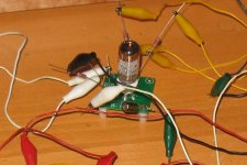
I put one of these together on breadboard (first picture). In order to keep the volume under control and not damage my soundcard, I ran the output through a 10K:150 parafeed transformer. I also used a 150V regulated supply as there were no 200V supplies within arm's length. And I used 1K grid stoppers on both grids. Otherwise, it was constructed as per the schematic.
First measurement is with the volume turned all the way up, second is with it turned all the way down with no other adjustments made.
First measurement is with the volume turned all the way up, second is with it turned all the way down with no other adjustments made.
Attachments
I have also used the 6j6 (elcheapo) as a driver for paralleled 6BX7 SE and it has proved to be outstanding.
Also used it on a 6ck4 SE as driver with excellent results.
This 6j6 is a good choice it gives a good freq. range to my ears IMHO.
Wavebourn is right on the money.
It may not be Audiophile style or grade, but unless you use them and tweak them you will never know.
Have a great DIY day
Michael
Also used it on a 6ck4 SE as driver with excellent results.
This 6j6 is a good choice it gives a good freq. range to my ears IMHO.
Wavebourn is right on the money.
It may not be Audiophile style or grade, but unless you use them and tweak them you will never know.
Have a great DIY day
Michael
Try this:
1. Adjust R5 for the minimum of higher order harmonics when 100K pot on the lower position (zero signal on the grid of the 2'nd triode),
2. Increase signal to the 2'nd triode's grid and see if harmonics go up on higher input signal.
3. If increase of distortions is not significant with input level try R3 of a bigger value.
4. If it does not work as intended discard it and wait until I experiment and find something better.
Thank you!
In which position was the pot on the schematic? What DC voltages did you have on anodes? Am I right (reading from your graphs) that the difference between "all the way up" and "all the way down" was only 10 dB?
Unfortunately, I took it apart already, and did not think ahead enough to record any voltages
But yes, about 12dB difference....
4. If it does not work as intended discard it and wait until I experiment and find something better.
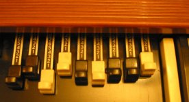
How about controls that work like these
Attachments
Unfortunately, I took it apart already, and did not think ahead enough to record any voltages
That means, it may be worked as intended: difference is visible. On lower levels higher harmonics should go away. I will experiment later with better amplification stage, but the similar reactive tube, to make it more variable.
How about controls that work like these
Too much.
- Status
- This old topic is closed. If you want to reopen this topic, contact a moderator using the "Report Post" button.
- Home
- Amplifiers
- Tubes / Valves
- Variable Harmonizer