
Cathode resistor will be below 1k.
are you sure ?
Just now looked at a design with 10K on ecc99
but also connected almost directly to other KT88 cathodes
which this is not, or at least not directly
I kept back for most of this.
But I just can't let this go:
Especially with a Circlotron style circuit,
where voltage references to ground may be ambiguous,
you absolutely must avoid an auto-transformer.
This is a death-trap,
just waiting for some child to tug a speaker-cable.
D.C. voltages stored in powersupply are just looking to empty themselves through some unforeseen or accidental connection.
The windings in the autotransformer will simply conduct DC.
As you can see from the schematic the center tap of the auto-transformer is grounded. I fail to see how you could generate any significant DC on the speaker terminals just by tugging the speaker cables.
Revintage ( Lars )
Since we slowly abandoned diff.amp (LTP) at input tube ,what do you think about two separate Ecc99 cathode ,each one with Rk as trimpot and with bypass 100uF elkos , and each one in series with small value resistor of 47ohm to ground , this two connection nodes to use for applying of low percent GNFB ? similar as is done in my schematic from post #133 at input Ecc81 tube ?
Best Regards !
As you can see from the schematic the center tap of the auto-transformer is grounded. I fail to see how you could generate any significant DC on the speaker terminals just by tugging the speaker cables.
For starters, suppose someone reverses a two-prong AC plug at the other end. Now 120 (or 240) volts is on the chassis, and through the few windings of the secondary will be on the speaker wire.
Thats why good practice says speaker lines be isolated by an output transformer,
and feedback loops should be done on a separate winding.
But why list all the possible things that could go wrong?
We all know they do.
And when they do, circuits designed with safety in mind
can save lives rather than destroy them.
For starters, suppose someone reverses a two-prong AC plug at the other end. Now 120 (or 240) volts is on the chassis, and through the few windings of the secondary will be on the speaker wire.
Maybe you have misread the schematic? The mains voltage is isolated from the chassis in the usual way. The autotransformer under discussion is handling the audio signal, not the mains supply. And it is grounded at the centre.
Chris
If you have no mains transformer -- but that's not usually the case..For starters, suppose someone reverses a two-prong AC plug at the other end. Now 120 (or 240) volts is on the chassis, and through the few windings of the secondary will be on the speaker wire.
And I would not be too concerned to use an autotransformer in a circlotron configuration like this.
And I would not be too concerned to use an autotransformer in a circlotron configuration like this.
other highly skilled members have told me the same thing
properly wired, grounded, etc etc, and theres not much to worry about
just the same issues like with any other 'normal' moderatly volatged tube
amp
thank you for this support
very appreciated
but, I still like the new schematic, with trafo wired like normal tube OPT
") especiall now I hear the lower impedance works even better
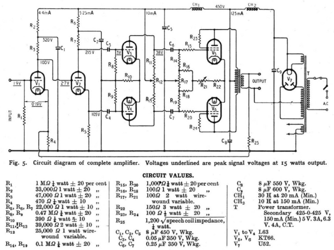
especiall now I hear the lower impedance works even betterSo once again, check the Williamson driver:
yes, I see it now
looks similar
but different tube, I guess
....what do you think about two separate Ecc99 cathode...
2x ecc99 per side
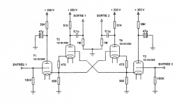
hmm, reminded me of this curcuit
we have looked at it before
I dont know what it is, how it works, or why
Attachments
...what do you think about two separate Ecc99 cathode....
or double penthode driver
maybe EL84 maybe a grid connection could be NFB
I have no idea tho
but with matching etc...money, money
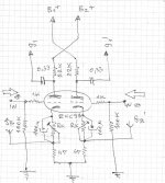
Here is my cirlotron circuit from some year ago: 6SL7 input, ECC99 driver and 6P45S final into a 600R OPT.
(I have to redraw that non-figurative art into some sort of a proper schematic..)
Think I got 50W+ out of it without questions. It's one of my frequently used amplifiers.
An externally hosted image should be here but it was not working when we last tested it.
(I have to redraw that non-figurative art into some sort of a proper schematic..)
Think I got 50W+ out of it without questions. It's one of my frequently used amplifiers.
An externally hosted image should be here but it was not working when we last tested it.
Last edited:
Jane
I like the simple way how you limited max.G2 disipation of 6p45c G2 with zeners !
and connected to opposite tube

- Status
- This old topic is closed. If you want to reopen this topic, contact a moderator using the "Report Post" button.
- Home
- Amplifiers
- Tubes / Valves
- Circlotron questions