"search the tube forum there's tons of info on input/ driver/phase splitter "
The usual driver/splitters aren't likely to work well here due to the Circlotron configuration requiring huge grid drive signals (50% CFB). We're in "Mac driver territory" here and we don't have a clue about the bandwidth of the OTs (or even their Zpri) or the amount of global feedback that was used before. Does anyone even have any data/curves for the output tubes? Maybe just use EL519 specs or similar.
(I'm also suspicious of the linearity of anything like the EL509/6KG6, maybe a change to another Sweep tube is all that's needed here.)
It should be possible to configure a bootstrapped driver stage, since it apparently had that before. But global loop gain/stability issues are unknown. For some real driver "grunt", something like a video pentode/triode 9 pin combo tube (9DX base) could keep to the original double 9 pin socket budget. High gm 5 Watt driver pentodes are readily available in this format, but could be difficult to tame their likely HF parasitics as well as the global stability issue. (the pentode would require some local Schade'ing to control loop gain and maintain the CFB output effect via plate Rp) Other, tamer, 9 pin candidates would be some of the vertical amp dissimilar dual triodes. Easier to configure if we know how much gain is acceptable.
One could approach this as a general Circlotron/Mac front end project for Sweep tubes. Except ---- Big big problem --- without test equipment available to the OP. An O'scope with HV probes, signal gen. and DVM are really mandatory here. Spice models for any of the likely tubes are almost certainly non-existant, besides the OT info, so Simulation modeling is out.
Thanks for the Response I think i can answer some questions...
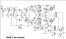
OT's are of the HIGHEST quality very very wide band width...and behave very well outside the audible ranges.. (squarewave) driving a 2mf 4 ohm loads...I seen all this... thats why i wanted them...
The Ot's have a switch 4/8ohm...LOOP feedback is around 13db with a simple resistor and its bootstrapped....
these are grid biased with separate neg supply adjusted via the 4 pots that you see in the amp.... I will take a more better pictures of the inside..
Lawrence
The primary impedance of the OT (and B+ voltage) is needed yet to determine open loop gain. Although the gains of the 12AX7 and 12BH7 give a good clue. Would be helpful to have a figure for the input signal to get some output level too. The high 12AX7 and 12BH7 Mu's appear to rule out the dissimilar dual Vertical amp triodes on second thought. Probably have to go with the Video amp dual dissimilars like maybe a 6LY8, 6JT8, 6KV8, 6HZ8.
I would start with the lower gm 6HZ8, it's also got the biggest driver pentode at 8 Watt. The others are all plug compatible 9DX socket tubes, so can try a frame grid version later by just swapping tubes. Maybe can set the triodes up similar to the original 12AX7, but run more current, say 2 or 3 mA each (adjust resistors for bias and plate load appropriately). Need to know how the original splitter was set up. A diff. stage with a CCS tail would be best here.
The pentode driver stage gets more complicated. It needs to have its output impedance lowered to keep the output stage's CFB operational with a bootstrap load on the driver plates. It also needs its gain brought under control for loop gain/stability. Local Schade'ing of the pentode drivers would be a typical approach to solve both, but that lowers the input Z of the driver stage and hence the loading on the triode stage (distortion issue). Another approach is to put the Schade networks back to the input triode cathodes, this avoids loading but is more tricky for stability, since it puts a high gain local loop in the works. How was the original global feedback connected?
Need to know if some Mosfets were used between the 12BH7 driver stage and output stage grids too. And what Mosfets. (input capacitance could have been excessive causing "slow" results maybe) And we need to know the grid input capacitance of the output tubes. How was the screen voltage for the output tubes derived? If this was a fixed voltage from ground, then we have UL mode in effect too with its Miller capacitance issues.
This may be a lengthy re-design process.
Last edited:
Maybe this can help : Circlotron Monoblock Power Amplifier
Attachments
That ECC99 dual triode driver looks very good, even pin compatible with the 12BH7 but much beefier. The Monoblock schematic could even be similar to the original design for Sk8Ter's amp. Certainly the simpler approach to take and more likely to reach success under the limited facilities available.
That ECC99 dual triode driver looks very good, even pin compatible with the 12BH7 but much beefier. The Monoblock schematic could even be similar to the original design for Sk8Ter's amp. Certainly the simpler approach to take and more likely to reach success under the limited facilities available.
Agree with you !
But just think that Sk8Ter 300 W Circlotron Amps run with much higher B1+/B2+ UBa , maybe even around 600V-700V , like it in this schematic simple solution for stabilization of output power tubes 160V Ubg2 suply over the two zener diodes .

The screen grid cross connection is a technique to keep the voltage from cathode to screen grid constant (for each output tube). Its actually connected indirectly to the same side cathode thru the floating supply. On the audio type tubes, this is usually just direct cross connected. For the Sweep type tubes, there is a voltage dropping zener to get the plate V down to the lower screen V. Although it's more common (than the Monobloc schematic setup shown above) to see a cross connected dropping resistor down to the screen with a zener from cathode to screen. If the floating plate supplies have a center tap voltage, then that could be used for the screen supplies instead.
Last edited:
Here is one more approved design of 140W PPP ( Circlotron ) Amp from Experience Electronics Germany which use audio type of output power tubes ,schematic is inside of PDF .
But there in schematic it is one obvious mistake related to signed voltage of 246V on the second half of the input Ecc83 anode, right value is 356V , this voltage is determined with four zener diodes string (D1 -D4) .
OPT Rkk Z is 330 ohm .
Best Regards
But there in schematic it is one obvious mistake related to signed voltage of 246V on the second half of the input Ecc83 anode, right value is 356V , this voltage is determined with four zener diodes string (D1 -D4) .
OPT Rkk Z is 330 ohm .
Best Regards
Attachments
Last edited:
is it normal practice to connect screen grid from one side to plate of opposite tube ?
I suppose this way its not 'triode-connected' ?
Triode connecting a pentode in a circlotron would be a waste, since the strong cathode feedback makes the characteristics of the output stage very linear and very low Zout. It acts like a really low mu, very linear triode anyway. You (or maybe just I) wouldn't want to throw away the advantages of the pentode, namely that you can saturate without pulling control grid current.
Basically, you would throw away a bunch of power for a very slight gain in linearity.
ah, now I remember
any cross coupling presents some risk of instability
and circlotron is natural cross coupled
does this mean feedback is 'a must', or... ?
No , Circlotron topology is natural Balanced Bridge PP circuit , and inherently is 100 % stable , Feedback (GNFB) is not necessary `must` at all .
Usually both half of Circlotron Balanced Bridge circuit is formed from two basic CF unit where each unit half already work with 100% of negative local feedback .
Best Regards
.... and inherently is 100 % stable......
glad to hear that
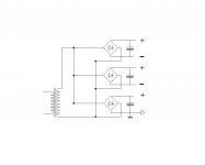
floating power supply
only having one trafo per stereo channel, I suppose its ok to use doube bridge and caps, one fore each output tube ?
I reckon input/driver should have their own seperate and grounded supply ?
being grounded, could that come from same trafo as above, but equally with own bridge/cap ?
btw, I have seperate heater trafo with CT, but unfortunately no CT on main B+ trafo
Attachments
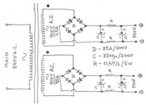
No , for each Circlotron channel you need two galavanic separate same value for main trafo secondary , so for stereo Circlotron Amp you need four galavanic separate same value trafo secondary , this PSU configuration it is for Circlotron Amp topology obligatory !
After rectification and smoothing capacitors Do Not connect both PSU B- on the main ground point , they have to be remain floathing ,same as for both B+ !
Important thing is to connect both main trafo secondary in the same manner to the SS rectifier ( in phase ) to get minimum hum ( PSRR issue ).
Not sure what kind of Circlotron Amp you want to made ?, OTL or OPT or ? ..., since for old style pentode Circlotron Amp you don`t need another separate PSU for input and driver stage , that come derived from the same output power stage Circlotron floathing PSU . Separate heater trafo with CT is OK !
Some schematic , or your start idea well be helpfull for future best PSU design .
Here is my old PSU schematic for Atmasphere M60 OTL Circlotron Amp ,attached here just for better Circlotron PSU understanding :
Best Regards
Attachments
Last edited:
No , for each Circlotron channel you need two galavanic separate same value for main trafo secondary
Not sure what kind of Circlotron Amp you want to made ?, OTL or OPT or ?
Some schematic......
ouch
 sounds like I will need new power trafos. Only have two with single secondary
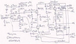
rough schematic of what I had in mind, (have the C3g and 6C19n)
OPT are 1.6Kohm PP
not small, and not exstremely big either
moderate output is my goal
obviously not the best way to start a project, with wrong parts
btw, we talked about the triode connected penthode, and I need to change that
Attachments
Yeap, mandatoryNo , for each Circlotron channel you need two galavanic separate same value for main trafo secondary , so for stereo Circlotron Amp you need four galavanic separate same value trafo secondary , this PSU configuration it is for Circlotron Amp topology obligatory !
. . .
PSUs not only need to be galvanicallly insulated but also must be able to really "float" within the whole frequency range of interest.
Choose transformers having low capacitance between windings (this excludes toroïds).
Yves.
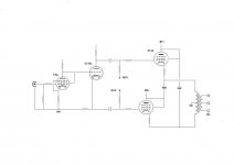
Tinitus if you insist on the Circlotron Amps with moderate output power and triode power tube for Circlotron output stage here is one schematic for you , unfortunately this amp need separate PSU for input and drive stage , but OPT it is just ordinary small 80-100w main power torus trafo 120v~/16v~ .
The whole article related to this schematic you can download from here : http://www.fonar.com.pl/download/circlotron6as7g.rar.
Best Regards
The whole article related to this schematic you can download from here : http://www.fonar.com.pl/download/circlotron6as7g.rar.
Best Regards
Attachments
Last edited:
Tinitus if you insist on the Circlotron Amps....
Best Regards
thanks for schematic
I was aiming at 15watt, or so
no, its not that I insist on circlotron design such
I thought it might be a way to use my 1.6K OPT
and get a bit more than 5watt
in excitement I got off on the wrong foot and bought all the wrong parts(a while ago)
if I have to buy too many new parts, I might better start completely from scratch
well, every time I believe to have learned something I only find that I know nothing, or at least still not enough
- Status
- This old topic is closed. If you want to reopen this topic, contact a moderator using the "Report Post" button.
- Home
- Amplifiers
- Tubes / Valves
- Circlotron questions