It is working now.Well, it's pretty. What exactly does/will it do?
and use bettery supply.
Attachments
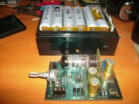
It is headphono Amp.and also can be a preamp.Looks like a headphone amp to me.


Member
Joined 2009
Paid Member
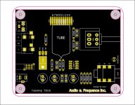
PCB and CASE already done.
Looks like the Indeed / Bravo headphone amps, only with the tube parallel to the PCB...
")
looks neat - is there a schematic, specifications ?

we are difference.Looks like the Indeed / Bravo headphone amps, only with the tube parallel to the PCB...


Hi ! grid current is about 2ma input resistance is 1M .Another Harmonizer? With a circuit like that it would be difficult to avoid distortion at the anode, and unless fed by very low impedance the valve grid current would distort the input too.
Do you mean anode current is 2mA? Grid current of 2mA would be extremely high!
Do you mean the grid resistor is 1M? The amplifier input resistance has the valve input resistance in parallel with the 1M. As the valve has no bias it will be operating well into the grid current region, which will impose a non-linear load on the input.
This unit looks very pretty, but I would expect significant amounts of distortion.
Explanation of the circuit
Basically, this is a grounded cathode voltage amp followed by an opamp buffer.
For full understanding ignore the opamp stage and look at the tubed voltage amp.
Just cut (in memory) the wire between the tube and the opamp (+) input.
The triode is fixed-biased by the grid-charge current that flows through the 1meg resistor.
To explain this:
The hot cathode always emitts some electrons that have enough energy to fly up to the grid.
The grid resistor closes the current path between grid and cathode so that the grid discharges across the resistor and
following Ohm´s law builts up a negative voltage between grid and cathode = ground.
This way of biasing works for many small signal tubes like 6DJ8, ECC88, 6922 but also for 12AT7, 12AX7 etc..
It works for pentodes as well, like DAF96, 1T4.
It won’t work for power tubes like 2A3 or so because the bias voltage is in the range of -0.3..-0.8VDC only.
Choosing the value of the grid resistor:
It´s written in the books. It is that value named “max. grid resistor” and often is combined with the type of bias: Automatic or fixed. Choose the value for “fixed”.
Here I have to correct myself:
If the book says “fixed bias” this is for an external negative voltage to be applied to the grid.
If the book says “automatic bias” this is for the bias acquired by a cathode resistor.
Most books don’t say anything about “grid-leakage bias” !!! If there is a value, use it.
If not: Use the value for automatic bias and multiply it by 10.
In my circuit the R1 value should be up to 10 megOhm .
The circuit works ok for R1 = 1megOhm but one can be sure that there is a small amount of grid current flowing.
Choosing a plate resistor:
Normally you would take the value off the data book, too. But in this case it is not possible because the plate voltage is so low that no curves exist for most
of the tubes.
Here is a procedure how to get a value without curve-tracing.
The plate resistor value is chosen that it will consume 4..6 V from the 12 V DC power. I recommed that this resistor is adjustable if you use any other tube than the 6DJ8
series or want to use other supply voltages.
Always adjust the plate resistor to consume 1/2 to 1/3 of the supply voltage.
If you try pentodes the plate resistor may consume up to 2/3 of the supply voltage.
Start with a high value, up to 200kOhm, and adjust to lower while continously measuring the voltage between plate and B+ until it fits.
Now take the adjustable resistor off the circuit and measure the resistance. You now may choose the standard value nearest to the result of the measurement.
An amplified input signal can now be seen at the opamp (+) input if we “repair” the wire we cut above.
The opamp in the prototype is an NJM4456 dual opamp. It is able to feed as much as 70mA into a 150 Ohm load.
The NJM is not as “hot” as modern opamps with enormous high gain-bandwidth products. So it is not very likely that you will have problems with noise or oszillation.
You may also try other opamps like NE5532 or OPA2134 or so. Make sure that they are “unity gain stable”. That means they will work flawlessly at a gain of 1.
That´s the configuration we need. We wire the output to the negative input and feed the signal into the positive input. From the DC point of view this input sits at
about 1/2 of the supply voltage, according how exactly you have chosen the plate resistor. In steady-state the output of the opamp follows the input (with a gain of 1 here)
and therefore sits at 1/2 of the supply voltage, too.
Side note:
You could use a standard buffer like the BUF634, too. It is more expensive, provides even more current and you need two of those.
The result is the same: The output follows the input and sits at 1/2 B+.
Ok. Here is another correction:
It was reported that the BUF634 would be outside a feedback loop and therefore is nearly incontrollable. It may work or not…
A better way is to put a MOSFET source follower as a buffer behind the opamp.
We do not like to feed the headphones with DC, so we need to go with an output cap.
Warning: Never go without output cap, otherwise your headphones (and probably your ears) will be ruined immediately.
You may use an electrolytic of 220uF for cans above 32 Ohms, like the PortaPro or SportaPro. You should use 470uF for lo-Z headphones.
Some people put a small film cap in parallel to the electrolytic to have better high frequency response.
Important: Watch the polarity of the cap. The + side of the cap goes toward the opamp output !
Essential are the two resistors after the cap.
The bleeder resistor:
This one, to ground, will allow the cap to charge at power on.
This helps to minimize the POP when you connect the headphones.
Side note:
You should connect / disconnect the headphones always if the amp is up and running.
You won´t notice POPs and this helps to preserve the sound qualities of the headphones.
The bleeder resistor should be about 10 times higher than the value of the headphone impedance plus the output resistor value.
The output resistor:
The output resistor is chosen between 22 and 150 Ohm depending on which final gain the amp should have.
The output resistor forms a a voltage divider together with the headphone impedance.
As a rule of thumb choose the low value for high-Z headphones (>=250 Ohm) and the high value for lo-Z headphones (32 Ohm).
Changing the value of the output resistor has _some_ effect on the sound and the stability of the opamp stage.
The NJM likes load impedances of 100 Ohm and higher best.
Chu Moy on July, 10th 2006.
Last edited:
It looks nice but of course is not finished.
To finish I'd remove the op-amp and add an SRPP output stage probably with 6N6p tubes and perhaps add a mains PSU so you can get about 300V of B+.
The whole deal about tubes in my opinion is to use them at the electro-mechanical interfaces;- so an output opamp is a big no-no in my book, the only use of silicon in my view should be in PSUs, constant current sections and the odd source follower.
I am very old though
Your build is very tidy and well executed, but I'd end up listening to the opamp, I like the batteries though - I'm sure ultimate fidelity will involve a box of 20 12V SLA packs one day for 240V pure DC rightness!
- Status
- This old topic is closed. If you want to reopen this topic, contact a moderator using the "Report Post" button.
- Home
- Amplifiers
- Tubes / Valves
- Just new one .all new layout.