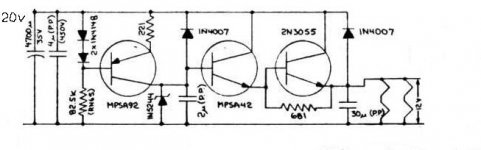
I realy like this zener heater regulator from Conrad Johnson using good quality capacitor… This schematic is from Premier 10 preamplifier, it is to drive two 6GK5 tube.
Do you think I can drive this tube with this schematic or I need to change something?
-One 12AU7 (300mA)
-One 12AX7 (300mA)
-Four EL84 (2x 800mA)
Total: 2.2A
2N3055 is good for 15A, this is not a problem but 681 Ohm is critical??? Maybe it is better to change the 4700uF for a much bigger value??
Thank you!
Attachments
I realy like this zener heater regulator from Conrad Johnson using good quality capacitor… This schematic is from Premier 10 preamplifier, it is to drive two 6GK5 tube.
Do you think I can drive this tube with this schematic or I need to change something?
-One 12AU7 (300mA)
-One 12AX7 (300mA)
-Four EL84 (2x 800mA)
Total: 2.2A
2N3055 is good for 15A, this is not a problem but 681 Ohm is critical??? Maybe it is better to change the 4700uF for a much bigger value??
Thank you!
It probably will work and the 681 ohms is not critical. But this is a very ancient circuit from the time that integrated regulators were not existing. A modern 12V LM7812-type regulator will perform much better, better regulaton and less noise and much smaller (a TO220). Maybe you should look into that too. You could even use individual regs for each tube.
I guess John Broskie has good circuits for that on his Tube Log site.
jd
What value is good for the input capacitor??? 12000 uF... more?
QUOTE]
What ever the 78xx datasheet says...
The .33 and .1 caps are just for stability and should be mounted as close to the regulator as possible, and each regulator should get them.
The main filter cap size depends on the input voltage. The higher you go, the less uf you need, but high value caps in this voltage range are cheap enough to use brute force here.
I'd start with 2,200 uf and see what happens. That's the value I used in my homebrew guitar amps, but I just sent dc to the preamps and used ac for the finals.
...or go for current rather than voltage regulation. Easier on the heaters at start-up.
arold19: do what aardvarkash said and forget the voltage regulation mumbo-jumbo. Depending on your input voltage you only need one power transistor per tube, a handful of resistors and a (small signal) reference transistor (or a pair of diodes or a LED or zener if you cannot find a suitable transistor anywhere in your junk box).
Read this check out section 5.0 in particular, the right current source type shown in figure 6a is what you should be looking for. Note that you can use your NPN transistors in place of PNP shown in this example if you turn the circuit upside down.
Making sense of whatever response one receives is always a smart thing to do !
After studying the difference between voltage and current regulation and comparison of circuit complexity and cost (like schematic in the first post + tens of millifarads worth of capacitance versus straightfoward two transistor CCS ?) I believe the answer should be rather obvious")
After studying the difference between voltage and current regulation and comparison of circuit complexity and cost (like schematic in the first post + tens of millifarads worth of capacitance versus straightfoward two transistor CCS ?) I believe the answer should be rather obvious
I realy like this zener heater regulator from Conrad Johnson using good quality capacitor… This schematic is from Premier 10 preamplifier, it is to drive two 6GK5 tube.
Do you think I can drive this tube with this schematic or I need to change something?
-One 12AU7 (300mA)
-One 12AX7 (300mA)
-Four EL84 (2x 800mA)
Total: 2.2A
2N3055 is good for 15A, this is not a problem but 681 Ohm is critical??? Maybe it is better to change the 4700uF for a much bigger value??
Thank you!
Why not just use a single LT1085-12 rated at 3A to provide power to all of them.. Much more convenient and all you need to do to get very close to 12.6V out is to put a 1N4001 in series with the ground leg of the regulator..
http://cds.linear.com/docs/Datasheet/1083ffd.pdf for data sheet for LT1085/84/83
Making sense of whatever response one receives is always a smart thing to do !
After studying the difference between voltage and current regulation and comparison of circuit complexity and cost (like schematic in the first post + tens of millifarads worth of capacitance versus straightfoward two transistor CCS ?) I believe the answer should be rather obvious
I am not a tube guy but constant voltage or constant current are so principly different, there must be some rationale why one would be recommended over the other. I would say that's the first question to answer.
After that, you can get fancy for that particular implementation. So, tube guys, CV or CC and why?
I know that CC is easier on the heaters because they are very low R when cold so with a CV supply the switch-on current pulse is probably huge. Can't imagine this is good for heater longevity, but as I say I'm not a tube guy.
jd
I am not a tube guy but constant voltage or constant current are so principly different, there must be some rationale why one would be recommended over the other.
There is. Multisection tubes have heaters either in parallel or series. For series heaters, a CC supply is best. For parallel heaters, CV is best. As will be no surprise to you, there's a pretty thorough explanation in Morgan Jones's "Valve Amplifiers."
After that, you can get fancy for that particular implementation. So, tube guys, CV or CC and why?
You explained it well yourself
Once stabilised, heater is just a piece of resistive wire, like its names implies. There is no difference between voltage and current feed as long as datasheet values are obeyed. Either value can be "dialed-in" once the tube heats up with either method but power-up shock will be taken by the transistor instead of tube filament when CC method is used, and it will be left to the tube for a second or longer duration when CV method is used.It is also worth adding that (like many things in audio world) this might be just a pointless precaution in some cases: when indirectly heated tube is used it makes little sense (but then again so deos voltage control as unregulated AC heater should work just fine if everything is designed correctly) because heater deaths are extremely rare (tube loses its emission capability much sooner than its heater terminates and loses continuity). This might not be the case for directly heated tubes which live better and longer without huge thermal shocks.
Current limit regulation protects from thermal shock when heaters are cold.
Voltage limit regulation prevents overheating. You benefit to have both.
I've wondered if heaters might be regulated as part of an autobias scheme?
Run em a little cold to extend life, till the emission inevitably starts to droop.
Then run em hot to squeeze every last bit of life before burn out completely.
An LED to warn they are on the last leg...
Wire like a fixed bias, your control circuit tweaks the heater(s) instead...
Maybe even forcibly match emission of mixed new and old tubes this way?
Last edited:
Kevinkr: I realy like the idea, it is very simple! I look at that!
Should work quite well, and the regulator will limit inrush currents to less than 3.5A typically which is quite a bit less than typical for an unregulated supply.
I will post a simple circuit that shows how to limit the inrush current using a single pnp transistor, an LT-1085 adj and a few resistors..
Current limit regulation protects from thermal shock when heaters are cold.
Voltage limit regulation prevents overheating. [snip]
I think they BOTH prevent overheating.
jd
- Status
- This old topic is closed. If you want to reopen this topic, contact a moderator using the "Report Post" button.
- Home
- Amplifiers
- Tubes / Valves
- Zener heater regulator