I am a relative newbie to circuit design and am trying to explain them to my readers in a way that is not too complex to understand. Attached is a schematic of a push-pull input stage with phase inverter. Is this diagram accurate as to the signal path outlines? Since half the signal has to pass through an additional tube, it is delayed relative to the other half, and this is called the dead time? Is there a way of correcting for this in an amplifier in some other part of the circuit?
Attachments
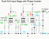
I am a relative newbie to circuit design and am trying to explain them to my readers in a way that is not too complex to understand. Attached is a schematic of a push-pull input stage with phase inverter. Is this diagram accurate as to the signal path outlines? Since half the signal has to pass through an additional tube, it is delayed relative to the other half, and this is called the dead time? Is there a way of correcting for this in an amplifier in some other part of the circuit?
"trying to explain them to my readers"

How are you going to explain circuits to your readers if you don't understand them yourself?
I recommend you educate yourself thoroughly before trying to explain this to "readers". You are not off to a good start with the concepts and diagram you're presenting so far. (and no simple correction or explanation is going to put you on track)
Try reading some of the threads here and study the sticky threads at the top.
Good luck and take your time. The journey is everything and it's no fun trying to be an instant expert ;-)
When you have actually designed and built and tested some amplifiers you will know what I'm talking about.
Michael
Last edited:
I have been reading the threads here. That is why I am asking the question. If the threads clearly gave me the answers I would not have posted the message. Take a look at my schematic, which was derived from a circuit posted elsewhere by someone who knows what they are doing, so presumably, the circuit schematic is correct. I just need to find out if the signal path I outlined is representative. Patronizing me only makes you look like you don't know the answers.
"Signal path" is a vague concept, so it's difficult to say if your outline is right or wrong. The whole "dead time" thing has to be nailed down better. Yes, there's another tube in the way, yes, it will have HF poles which will cause a slightly different frequency response on that side, no, it has nothing to do with any "dead time" or "transit time" or delay (beyond the extra HF pole).
What you have there is a very mediocre circuit- there are far, far better ways of doing well-balanced phase splitting. There's an excellent survey of the various means, their operation, and advantages/disadvantages in the classic book "Understanding Hifi Circuits" by Norman Crowhurst. Easy to get a copy from Amazon and would very much be worth your while.
What you have there is a very mediocre circuit- there are far, far better ways of doing well-balanced phase splitting. There's an excellent survey of the various means, their operation, and advantages/disadvantages in the classic book "Understanding Hifi Circuits" by Norman Crowhurst. Easy to get a copy from Amazon and would very much be worth your while.
Patronizing me only makes you look like you don't know the answers.
Michael is well known here as an experienced and knowledgeable guy. You're not likely to get far with statements like that.
I'm with SY and Michael - you have chosen probably the most complex single phase inverter design to analyze, and you've done so without any real knowledge.
Go to the source(s) - and there are plenty...
www.valvewizard.co.uk is a good souce of basic info on all stages of an amp
audioXpress - Track Listings - Audio Classroom Series are Norm Crowhurst's somewhat definative series on hte same subject
Steve's Tube Pages Steve Bench also gives a pretty thorough once-over on hte subject along with many many many others...
.
What you have there is a very mediocre circuit- there are far, far better ways of doing well-balanced phase splitting.
Medioce? I'd go as far as to say PITIFUL. There are many many ways to phase split better than that.
Regards, Allen
LTSpice and vacuum tube models simulation is another aid to understanding and teaching
Since the circuit is going from single ended to complemetary signals, I think it would be more clear if you kept the ground path as a zero reference throughout instead of showing it as an inverted path.
The 1st two tubes actually are doing inversions (cancelling out) as well as the final tube, not sure if you want to indicate that feature or are more interested in just showing the signal flow. The final tube, V3, is the one that does generate the relevent inverted output signal. Its grid takes in the forward path signal and an inverted feedback signal from the grid resistors. It's net gain is designed to end up with an identical but inverted signal on its plate.
The transit/transmission times (not really any "dead time" here unless maybe you are referring to the feedback signal not being perfectly coincident with the input signal, again insignificant nanoSec realm) here are really very insignificant compared to any audio frequencies. (nanoSec realm) Distributed and tube Miller capacitances are the more significant issues which end up producing phase shifting at high frequencies (hopefully well above the audio band if designed competently), and could cause the non-identically processed signals to go out of phase at HF.
Additional complaints about the quality of the inverter are related to the inverted signal having been affected by an additional, slightly non-linear, transfer function in the V3 tube which causes some mismatch with the other output. Also that the V3 grid resistors have to be tweeked to get identical output gains (depending on V3 gain), and aging of V3 may cause some drift in this matching over time as well.
my $.02
Edit:
I just noticed that there is No feedback in the inverter stage shown. Usually the V3 grid resistor shown to ground, which acts to form an attenuator (to null out V3 gain) in this diagram, is connected to the inverted output to provide some feedback linearization. Nevermind my comments about the feedback issues. But with V3 operating open loop like this, there will be some noticeable distortion from V3. And the gain of V3 is just being tossed out instead of performing some useful linearization action.
If the additional transmission time thru V3 really were a significant concern (it isn't), one could put another tube stage (non-inverting) in the original signal output path to equalize the transit times of both outputs to fix it up. Doing so for an audio amp might get you committed to the nut-house though.
Last edited:
Take a look at my schematic, which was derived from a circuit posted elsewhere by someone who knows what they are doing, so presumably, the circuit schematic is correct.
You don't know what you're doing, so how can you tell? Why not just tell your 'readers' the same truth that you told us; 'I am a relative newbie to circuit design'? Post a link to this site, where they can learn from the horse's mouth. Then there'll be less likelihood of transmitting a misapprehension.
w
That circuit was supposed to be a bad design. That was the whole point. I need a circuit that is going to produce very poor crossover. From your posts, I think the signal path is correct. That is all I wanted to know.
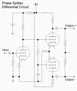
Now, here is a phase splitter that is also differential, which would give a better crossover in the push pull output stage. Do you see anything that should be changed?
Now, here is a phase splitter that is also differential, which would give a better crossover in the push pull output stage. Do you see anything that should be changed?
Attachments
I have an additional question that I could not find the answer for. Push pull amplifiers require phase splitters at the input stage, but in the output stage, the signals are in phase. One side handles the + portion of the waveform, and the other side handles the - portion. Why is it necessary, then, for there to be a phase inverter/splitter at the input stage, and how are the signals made to become in phase between the input stage and output stage?
Just to complicate the matter you don' have to phase split it's called single ended ..LOL
Sorry couldn't help myself
Regards
M. Gregg
Sorry couldn't help myself
Regards
M. Gregg
I have an additional question that I could not find the answer for. Push pull amplifiers require phase splitters at the input stage, but in the output stage, the signals are in phase. One side handles the + portion of the waveform, and the other side handles the - portion. Why is it necessary, then, for there to be a phase inverter/splitter at the input stage, and how are the signals made to become in phase between the input stage and output stage?
I'm curious as to what you think "crossover" means. Are you trying to teach your readers how not to design circuits, how not to understand them, and how not to describe them in terms understood by other people? Is this all some sort of wind-up? Please reassure us that you are just a journalist, and not attempting to write some sort of textbook!
That circuit was supposed to be a bad design. That was the whole point. I need a circuit that is going to produce very poor crossover. From your posts, I think the signal path is correct. That is all I wanted to know.
Crossover? Do you mean "phase splitting?" Gotta get your terminology correct if you want to be understood.
In any case, that's a better circuit, but the devil's in the details.
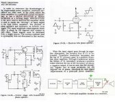
I put together a graphic that shows some information from the US NAVY electronics training manual to help explain where I am confused. I understand that the original signal, let's call it a 1 kHz sine wave, goes through the splitter, and it ends up at two outputs. Each is the sine wave but each is 180 degrees out of phase with respect to the other. In timing, they begin at exactly the same point, and they are fed to the output stage. OK, so now look at the block diagram at the bottom right corner. My confusion is how the first (positive) half of the waveform in the + portion of the leg (green at the top) ends up at the output in its same phase, while the second half of the waveform, handled by the - leg (red, at bottom) ends up at the output inverted again, so that it is in proper phase relationship to the first half of the waveform.
Attachments
If you are familiar with how humbucking guitar pickups work it’s partially analogous to PP amp sections. Each side of the PP output is connected to opposite ends of the output transformer. So each need to be fed, and needs to output signals that are out of phase since one side needs to push the current thru the tranny while the other is pulling it. Think about 2 lumberjacks using a double handle saw. One pushes while the other pulls since they are on opposite ends of the output/blade. Forget about "top half" and "bottom half." Only class B is exactly like that. Class A lumberjacks are both pushing/pulling at all times. Class AB lumberjacks each take a short rest near the end of their respective "pull" ends.
I'm a lumberjack and I'm ok….
I'm a lumberjack and I'm ok….
Look at the transformer phase splitters on the lower left. Phase-split push pull power stage drive is necessary because there are no P type electron tubes. In the output section each power tube drives the opposite end of a center tapped winding. The primary legs on the transformer then run like a see saw, when one tube plate goes down, the other goes up. A single winding on the the secondary of course outputs a single phase, either "0" or "180" degrees, your choice.
- Status
- This old topic is closed. If you want to reopen this topic, contact a moderator using the "Report Post" button.
- Home
- Amplifiers
- Tubes / Valves
- Dead Time - Correcting for it