I have ordered an Arduino for messing with, and the chip it's based around is available very cheaply. I was thinking about making some kind of overall amp control thing that could include: an HT delay (not necessarily because of the cathode stripping myth), output relay, bias monitoring (using the inbuilt ADCs in the chip), individual tube status LEDs, imagination is the limit!
It sounds like great fun to play with and I can't wait until it arrives to be honest!
Has anyone else played with this kind of thing? Did it turn out to be overkill or did it prove itself as useful?
It sounds like great fun to play with and I can't wait until it arrives to be honest!
Has anyone else played with this kind of thing? Did it turn out to be overkill or did it prove itself as useful?
813 SE triode amps
A processor in an amp is very interesting, I think. Seems like they are in just about everything these days, except for food and hand tools.
A processor in an amp is very interesting, I think. Seems like they are in just about everything these days, except for food and hand tools.
I have ordered an Arduino for messing with, and the chip it's based around is available very cheaply. I was thinking about making some kind of overall amp control thing that could include: an HT delay (not necessarily because of the cathode stripping myth), output relay, bias monitoring (using the inbuilt ADCs in the chip), individual tube status LEDs, imagination is the limit!
It sounds like great fun to play with and I can't wait until it arrives to be honest!
Has anyone else played with this kind of thing? Did it turn out to be overkill or did it prove itself as useful?
I have used PIC micros in my designs for a good while now.
Output relay control (power up delay).
DC protect supervision controlling output relay.
Bar graph driver.
Check out this link: 813 SE triode amps
I think it would be great to have something to adjust fixed bias automatically. I'd be curious if I could do that with an anti-thermistor
I think it would be great to have something to adjust fixed bias automatically. I'd be curious if I could do that with an anti-thermistor
The ATmega32 only has 8 muxed ADC inputs, so you'll need to add more muxes if you want to dip your hand into every single part of the amp. It has no onboard DAC, so if you want to adjust things, you either need a particularly good lowpass filter to clean up the PWM channels (2 x 8-bit, 2 x 16-bit), or an external DAC (parallel or serial, and the ability to program it).
Tim
Tim
The arduino mega (based on the atmega1280) is a much more "useful" uC, though the 128/328's found on the smaller unit's have there place to I suppose.
C# is my forte, But I really don't see the use of a uC in a tube amp, the highest logic level you could ever need would be a "re-purposed" 555 timer to generate PWM for cooling fans")
I digress, The use of a uC to do nifty reporting of tube bias and voltage might not be so bad, but the thing about tubes that interest me, is there mechanical nature, so a good vintage bias meter, and voltage meter, to me, is more par for the course.
IMHO
YMMV
C# is my forte, But I really don't see the use of a uC in a tube amp, the highest logic level you could ever need would be a "re-purposed" 555 timer to generate PWM for cooling fans
I digress, The use of a uC to do nifty reporting of tube bias and voltage might not be so bad, but the thing about tubes that interest me, is there mechanical nature, so a good vintage bias meter, and voltage meter, to me, is more par for the course.
IMHO
YMMV
Micro's are the bomb for housekeeping.
I have built a couple of guitar amps that used gates and flip-flops to control channel switching, but now I'm working on a multi channel version with some built in effects and, using logic ic's, the schematic is taking over my desk.
A micro is the only practical solution in my case.
I have built a couple of guitar amps that used gates and flip-flops to control channel switching, but now I'm working on a multi channel version with some built in effects and, using logic ic's, the schematic is taking over my desk.
A micro is the only practical solution in my case.
Micros + tubes = versatility. Whether this versatility is useful or not is up to the user.
In the live performance for musical instruments arena it is almost a necessity. Commercial "midi tube preamps" have been around for a long time. I have an old ADA MP-1 that I have used for about 10 years, and I got it used on Ebay. It uses a micro to control a pair of 12AX7's. You can tweak the controls until you find the sound of your dreams and save it in memory. Then one stomp of a pedal and this sound is back. Several sounds can be stored and recalled at will in a live performance situation. The MP-1 is an old design and the user interface sucks. SO.....I designed my own. It used a bit more sand and it was 10 years ago, but it used a PIC16 series chip controlling some National Semiconductor EQ and gain control chips in the forward and feedback paths of a tube preamp. There is a new one in the works using much more modern parts, and it goes inside the guitar, and so does the tube preamp. It deserves to be seen, so I built my own guitar with a clear Lexan pick guard to show off the chips, mosfets, and tubes. It won't be done for a while, but it will be seen here when done.
In the home HiFi world a micro can easilly handle bias control, power supply sequencing, and even store setups, data log bias voltage VS tube current to report tube condition to the user. You could even use your amp to match tubes. How far can the micro go in a tube amp? Well you could use a specialized micro like a dsPIC to design a modulated SMPS for serious efficiency improvements. Sound far fetched? Not really, I built one of those too. It won a prize in a Circuit Cellar design contest. Details, including the entire project submission is here:
Microchip 16-bit Embedded Control Design Contest
I have ordered an Arduino for messing with, and the chip it's based around is available very cheaply. I was thinking about making some kind of overall amp control thing that could include: an HT delay (not necessarily because of the cathode stripping myth), output relay, bias monitoring (using the inbuilt ADCs in the chip), individual tube status LEDs, imagination is the limit!
It sounds like great fun to play with and I can't wait until it arrives to be honest!
Has anyone else played with this kind of thing? Did it turn out to be overkill or did it prove itself as useful?
Yes, why yes I have played with what you speak of quite a bit. I built a control unit for my GM70 amplifier that operates as a start up sequence (and shutdown) to warm up the 866A's start all the filaments in sequence then apply the high voltage. It also monitors voltages calculaes cathode current and displays everything on the LCD. I have attached pictures of my working prototype. As you can see I built the Arduino board myself. You buy the chip with the boot loader and a couple bucks in parts later you have a working board. It sits on the main board via some headers so it can be taken off and programed. I was going to put a max232 chip on there but never got around to it. The first 3 relays put out 120v to go to the various transformers and the other 2 are input output relays.
The voltage monitoring gets a bit tricky as the max voltage you can apply to the analog i/o's is 5 volts so you have to use voltage dividers and some math in the sketch.
Not included in the prototype is the ability to adjust bias on the fly but I though of two different way of doing it. First way would be a simple CCS circuit with a 10M45 and an alps electric potentiometer (or 2$ servo hooked to a regular pot). That would be good upto 100ma. My second idea was to use a stepper motor connected to a rotary switch with LED's between steps to ground.
I will not go on too much but would be happy to answer any questions or share code with you as I have gone though a lot of trial and error here. I am currently working on porting over all my code to the Arduino ATmega1024 and 128X64 display so I have more i/o's and a real fancy display.
An externally hosted image should be here but it was not working when we last tested it.
An externally hosted image should be here but it was not working when we last tested it.
Care to share the source code w/us? Ill help you finish this project up.
also, instead of using a boot loader, why not get a avrisp mkII and use avrdude to do the uploading, nothing wrong with the arduino stuff, but a boot loader is for noobs, your already playing with high level logic, and high voltages, so your not a noob.
Love the idea though.
also, instead of using a boot loader, why not get a avrisp mkII and use avrdude to do the uploading, nothing wrong with the arduino stuff, but a boot loader is for noobs, your already playing with high level logic, and high voltages, so your not a noob.
Love the idea though.
Care to share the source code w/us? Ill help you finish this project up.
also, instead of using a boot loader, why not get a avrisp mkII and use avrdude to do the uploading, nothing wrong with the arduino stuff, but a boot loader is for noobs, your already playing with high level logic, and high voltages, so your not a noob.
Love the idea though.
Here is where my code gets heckled by people who know what they are doing
Keep in mind that 8 months ago I had no idea what a microprocessor could do, how to program C or what an Arduino was. It has been a pretty steep learning curve but I have had a bit of help from a friend who programs C and Java. All and all I am pretty much a noob just one who learns fast.
I do have to learn about avrdude and non-bootloader stuff as I bought some SmartLCD boards for another non-tube related project. I really have to get going on them soon.
For the sake of brevity I will zip the basic sketch for the start-up sequencer, the sketch for the voltage monitoring and the timer library. I have them all combined into a sketch but its at home on my laptop and its probably better to look at them separately. I may have changed a few things since then as well.
http://shaneaune.com/images/voltage.zip
http://shaneaune.com/images/startstop.zip
http://shaneaune.com/images/Timer.zip
Yea, kinda messy, Ill clean it up for you today, and streamline it. also, iv got a arduino mega engineering sample board here, and a serial 128x64 GLCD I can help you finish the upgrade process.
ANY uC issues you have, just ask, or shoot me a pm, I was one of the original atmega 1280 porting programmers on the arduino project, thats why my arduino mega pcb is red
ANY uC issues you have, just ask, or shoot me a pm, I was one of the original atmega 1280 porting programmers on the arduino project, thats why my arduino mega pcb is red
Yea, kinda messy, Ill clean it up for you today, and streamline it. also, iv got a arduino mega engineering sample board here, and a serial 128x64 GLCD I can help you finish the upgrade process.
ANY uC issues you have, just ask, or shoot me a pm, I was one of the original atmega 1280 porting programmers on the arduino project, thats why my arduino mega pcb is red
Sweet, I will get my board together at home and shoot you a PM.
I would really like your input on the SmartLCD stuff on how I get started with avrdude. Since I really have very little background in this stuff sometimes I feel like I am stabbing around in the dark. When I was trying to get a bmp to show on my 128X64 display it took me a couple of days to figure out that the "Processing" part referred to a different program, not the Arduino sketch loading program. I felt pretty silly after but sometimes when your trying to learn something just off the internet you hit some real simplistic dead ends.
Hi, I am also interested to utilize micro controller in DIY pre amp/power amp. I think it can be used to control bias, gain, fan speed, themperature (using e.g. LM35), voltage and current monitoring, feedback etc. Not sure if such project already exists.
I just bought AT8535 micro kit, and found it very easy to program with (since it almost contains everything in one chip), and quite cheap. But not yet to integrate into DIY audio, currently just for trying/experiment.
Ervin L
I just bought AT8535 micro kit, and found it very easy to program with (since it almost contains everything in one chip), and quite cheap. But not yet to integrate into DIY audio, currently just for trying/experiment.
Ervin L
I hate to dig up old threads, but this is exactly what I want to do (although with a MSP430 and an OLED display). I mainly want to monitor voltages, which means up to 500V DC. I'm fine with using a voltage divider for my ADC. My question is if the microcontroller will introduce any unwanted noise? I originally wanted the entire unit to be on an isolated ground, but that involved optocouplers and many other complexities. I also want to be as safe as possible. My current plan is to have the MCU, circuitry and display all within the tube amp chassis. I won't have/need any buttons or controls (displays will be fixed).
If anyone is still around from this original project, could you post a simple schematic of how you hooked everything up? Did you use any protection diodes on your high voltage inputs into the MCU (after the voltage divider)? Were your MCU and amplifier powered from the same source? How did you handle the Star Ground?
Thanks!
The ATmega32 only has 8 muxed ADC inputs, so you'll need to add more muxes if you want to dip your hand into every single part of the amp. It has no onboard DAC, so if you want to adjust things, you either need a particularly good lowpass filter to clean up the PWM channels (2 x 8-bit, 2 x 16-bit), or an external DAC (parallel or serial, and the ability to program it).
Tim
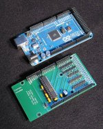
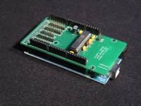
Here's an 8 channel 10 bit DAC Arduino Shield I built to control my Internet of Things tube tester.
http://www.diyaudio.com/forums/tubes-valves/206787-micro-programmable-tube-tracer-tester.html
This goes onto the Arduino Mega board. The design took me a couple of hours at most as I was able to download PCB template for the Mega board and only needed to make the AD7808 symbol. The wiring is literally 6 or 8 nets total.
The Arduino code is based on Processing but for C and is totally easy to get up and running in just another couple of hours if you have any coding experience at all.
Attachments
- Status
- This old topic is closed. If you want to reopen this topic, contact a moderator using the "Report Post" button.
- Home
- Amplifiers
- Tubes / Valves
- Microcontrollers in tube amps