It occurs to me that it might be good to combine the advantages of Garter bias (good DC balance) and CCS bias (good AC balance) for Class A triode PP. I'm not sure how this could be achieved in practice but I'd love to see ideas on this.
Done with bypassing referenced to each other, the CCS addresses both AC and DC balance, but you are restricted to class A.
Shoog
I think Ken's drawing will just supply constant current (and zero current at that unless they are depletion mode, 10M45 is depl.) to each tube since there is no feedback path that gets around the Hi-Z Fet drains. The Fets are doing there own thing, could care less what the tubes are doing.
I think it needs to have the Fets and Source resistors turned upside down and use P channel parts. Then the tube currents will affect the Fet biasing. Maybe have to move the grid bias pickoffs up to the resistors too, then maybe not, could work as is if too much voltage is not lost in the Fets.
I think it needs to have the Fets and Source resistors turned upside down and use P channel parts. Then the tube currents will affect the Fet biasing. Maybe have to move the grid bias pickoffs up to the resistors too, then maybe not, could work as is if too much voltage is not lost in the Fets.
Last edited:
Split tail pair has two DC constant current sources. And in this case,
Garter matched 10M45S sources no less! (yes they are depletion w.
approximately -5Vgs threshold)
But we also have a capacitive path across the top, for AC currents
to pass back and forth, from one cathode to the other, in Class A...
Just as they would for AC with an ordinary single CCS, long tail pair.
The usual Garter bypass caps to ground would be redundant to the
function of caps bridged across the top. Adding caps to GND would
inhibit forced AC balance that Ray specifically asked for.
The example above would pass about 100mADC quiescent per tail.
Yet due to the AC cap bridgeage, both tails could be servicing one
triode to swing 199mA while the other swings 1mA. Then vice versa...
The triodes must require a negative bias high enough to drop 10V in
the garter and at least another 10V (or is it 15V?) in the drain. So
we not talking a circuit ready for just any old random triode. It has
to be one that likes at least -25V on the grid, even at highest peak.
I can show you slightly more complicated split-tail of garter matched
Aleph current sources. If -25V bothers you, the Aleph only needs 5V
to function. I showed you the 10M45S first, because it was simplest.
Garter matched 10M45S sources no less! (yes they are depletion w.
approximately -5Vgs threshold)
since there is no feedback path that gets around the Hi-Z Fet drains.
But we also have a capacitive path across the top, for AC currents
to pass back and forth, from one cathode to the other, in Class A...
Just as they would for AC with an ordinary single CCS, long tail pair.
The usual Garter bypass caps to ground would be redundant to the
function of caps bridged across the top. Adding caps to GND would
inhibit forced AC balance that Ray specifically asked for.
The example above would pass about 100mADC quiescent per tail.
Yet due to the AC cap bridgeage, both tails could be servicing one
triode to swing 199mA while the other swings 1mA. Then vice versa...
The triodes must require a negative bias high enough to drop 10V in
the garter and at least another 10V (or is it 15V?) in the drain. So
we not talking a circuit ready for just any old random triode. It has
to be one that likes at least -25V on the grid, even at highest peak.
I can show you slightly more complicated split-tail of garter matched
Aleph current sources. If -25V bothers you, the Aleph only needs 5V
to function. I showed you the 10M45S first, because it was simplest.
Last edited:
My mistake: According to 10M45S spec sheet, 100mA is achieved at -2Vgk.
The -5Vgk spec I recalled from flawed memory, was for 0mA total cutoff...
The resistors in the garter would be only 20 ohms. And only 4 volts dropped
in the garter. The spec sheet is far from clear about how many volts needed
to be standing on the anode to achieve 100mA @ -2Vgk? The smallest number
given for an anode voltage is 10Vak. Yet current vs Vgk curve was probably
drawn for conditions at 450Vak. I'm thinking 15Vak+4Vgarter is still safe bet.
So thats 19VDC cathode bias, bare minimum to maintain regulation in garter.
I still need to show you the Aleph version.
Last edited:
Done with bypassing referenced to each other, the CCS addresses both AC and DC balance, but you are restricted to class A.
Shoog
Agreed, Class A is enforced by a common CCS. I strongly suspect the same is true with Garter bias too. That's fine with me.
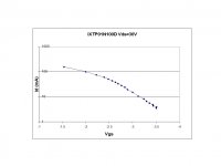
My experience with 10M45s is that they won't go to 100mA without Vgk going positive. They don't follow the published curve at the higher currents, at least at up to 50Vak. By that voltage the Vak should be saturated.
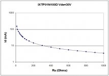
I tested the newer IXTP01N100D from IXYS and it easily reached 100mA at 30Vds.
I don't know why they call the terminals "A" and "K" either, being a depletion mode N-MOSFET it has a drain, a gate, and a source...
(the garter circuit) "AC balance has to be inferior to the CCS versions"
Shoog, what is it about AC performance that has to be inferior and why? I don't get it.
Attachments
Enhancement mode opens more MOSFET choices.
IRFP240 (200V) probably works fine here? No sense to
specify drain Voltage that greatly exceeds the cathode
bias and/or bridge electrolytic ratings. Drawing shows
a 600V mosfet, is probably overkill.
This the Aleph version I was goin' on about earlier...
You need about 1.34 Volts to bias the garter. Then
whatever small amount dropped in RDSon.
Though several wizards of solid scrape have warned
against operating MOSFET with fewer volts on drain
than gate. Miller capacitance Cdg goes up greatly,
so CCS may react more slowly if not enough Volts
are present. Give it about 9V to properly shape the
depletion region, and Miller should be OK.
Talking about minimum 10V cathode bias if we want
this to really work well. I could claim it works to 2V,
but might be kinda mushy for reasons as given...
Attachments
Last edited:
Shoog, what is it about AC performance that has to be inferior and why? I don't get it
Any CCS is going to exhibit a higher impedance at AC than the pair of resistors used in the Garter belt. This should impose stricter current transfer between the cathodes (via the caps). The Garter could allow imbalance to escape to earth via the low resistance path.
My experience is that the Garter sounds fine all by itself, so I suppose its a theoretical concern more than an actual one.
Shoog
Last edited:
Anyone tried this biasing in real amp? I did experimented the 10M45 Cathode CCS for an EL84 PP amp. It was very simple with two 10M45's in parallel sharing the two EL84 current at 65mA each. There was no bypass capacitor across the CCS at all. The result was pretty with very clear and open sound stage.
Johnny
Johnny
Any CCS is going to exhibit a higher impedance at AC than the pair of resistors used in the Garter belt. This should impose stricter current transfer between the cathodes (via the caps). The Garter could allow imbalance to escape to earth via the low resistance path.
This is CCS, well two. I don't get why garter match makes it any less CCS?
Where is this "low resistance path"?
We aren't garter matching Triode cathodes with low Z resistor directly. We
are garter matching CCS, presenting cathodes with a high impedance drain.
Why should Parallel Z of two tails be less than half a single current source?
All currents in both paths are fully accounted for. Where is the low Z leak?
This ain't yer grandma Blumlien's garter (no bypass caps to GND)...
Last edited:
I suspect the original idea may have been to put a single CCS under a standard Garter circuit for the tube balancing, rather than a Garter on the CCS biasing. Ken's dual CCS circuit should work fine with high Z for AC balance. But the CCS Garter part seems a bit pointless. Just set the two CCS's up for the same current to begin with. (Well, OK, you would have to adjust a pot for DC balance then I guess if you didn't have matched Fets (but bipolar CCS's should match well enough).)
I think he is comparing the OPs circuit (using CCSs) with a traditional garter using only four resistors.This is CCS, well two. I don't get why garter match makes it any less CCS?
Where is this "low resistance path"?
Also, why is it called a Blumlein garter? I've seen most (all?) of the publicly available circuits by Blumlein, and I've yet to see the garter used in any of them??
I think he is comparing the OPs circuit (using CCSs) with a traditional garter using only four resistors.
Indeed thats what I mean't, crossed purposes.
I really can't see any advantage in adding the Garter to the CCS with cross referenced caps.
Shoog
If you are only building one or two, and don't mind rough
matching your sand, and adding a tweak pot... Yeah, no
"advantage" adding a garter match to the twin CCS.
Then again, if you building a hundred. And don't want to
match or tweak anything. Need it to automagically work...
FET threshold much worse variance from batch to batch
than tubes. Within the same batch, they can be OK. If
using only depletion FET (post#2), you should definitely
tweak a match if you don't garter.
BJT 0.66V threshold is pretty consistent, the Aleph variant
exploits this advantage to further enhance the match. BJT
definitely have huge variations in Beta, this circuit pretty
much don't care what is Beta... You might not "need" the
garter nor tweak with Aleph current sources, but its only
2 resistors and 0.66V more to add that insurance.

Garter effectiveness tested with deliberately mismatched sand.
This analysis from an old debate I once had with Nelson Pass.
Don't remember all the specifics anymore, hope it explains itself.
Aleph already seems to have taken care mismatched MOSFET.
The garter though, helps a lot with the mismatched BJT.
In light of bypass caps across the top, I don't think bypass
caps in the garter do anything helpful. But this was probably
drawn long before I came to that conclusion.
Attachments
Last edited:
Belated thanks to everyone for your excellent comments. It all makes good sense and I'm especially grateful to Kenpeter for the circuit. Modeling this, it seems to deliver a good result with triode strapped EL34s at 435v B+ (400v plate-cathode) using IRFBC20 MOSFETs and 10 ohm resistors R1 - R4.
- Status
- This old topic is closed. If you want to reopen this topic, contact a moderator using the "Report Post" button.
- Home
- Amplifiers
- Tubes / Valves
- Triode PP OP stage combining Blumlein Garter and CCS bias - anyone tried this?