Hello
I am trying to use an analog meter with a dB scale to measure the output of an amp or source (ipod). I would like to incorporate this meter into my tube power amp or pre-amp.
Here is my setup: Unknown dB meter with a diode (1n4007) feeding the positive side. ground to the negative side.
So far the results are that the meter reading is too low and the resulting sound has an added distortion.
I am trying to keep this all tube so I am guessing that it will be suggested to use a buffer (common cathode?) to fix the problem. But will this help since common cathode provides no gain. will I need to use a buffer and then an amplifier stage?
Also where is the correct place to take my reading from? right before the output tube?
Thank you
Yes you need a bridge rectifier if you expect proper readings. The 3.9k series resistor is needed too; with it you will not hear any distortion. In the reference from tomchr the Fig. 1 is the classic circuit. The usual reading is 0.775 Volts for 0 VU if I remember correctly. This would give proper readings on a 600 Ohm line. That is, one milliwatt at 0 VU if my offhand mental calculations are correct.
If you are measuring a power amplifier, you will need an attenuator else you will peg the meter on anything over 2 mW (referred to 600 Ohms).
That is what a VU (volume unit) meter does. Perhaps all you want is a voltmeter, or a wattmeter.
If you are measuring a power amplifier, you will need an attenuator else you will peg the meter on anything over 2 mW (referred to 600 Ohms).
That is what a VU (volume unit) meter does. Perhaps all you want is a voltmeter, or a wattmeter.
...
So far the results are that the meter reading is too low and the resulting sound has an added distortion.
You are not placing the meter in the signal path are you? Build a small amp (a simple triode gain stage) that drives the meter only. I think it might be best to use more gain than you need then use a voltage divider to scale to whatever the meter needs. You might use to pots, one for gain and one for zero adjust.
I think the diode is there because the meter reads DC and the diode converts the AC signal. But a 4007 is non-linear at very low volts until it starts conducting.
Here's one: VU And PPM Audio Metering
thankyou I have looked at this site before and will give the first version another try with Ge diodes.
You are not placing the meter in the signal path are you?
I am taking my reading from the output of the driver stage after the cap before the power tube grid.
You are not placing the meter in the signal path are you?
ok so say a dual triode setup with the first stage as a cathode follower and the second as a regular amplifier stage to drive the meter? Ill see if I can build it today and report back. thank you!
I'd drive the meter with a cathode follower as the meter circuit will be low impedance.
Driving it from the driver stage will peg the meter if it is from a power amp as you will see anywhere from 10Vrms up depending on the output tubes.
You will need to scale the drive to get the meter to corrospond to your intended purpose.
I've got a pair from a casette Player I stripped that I considered using as power VU meters by scaling the 0dB point as max output before clipping.
Then I realized the filter effect of the mechanical movement would dampen the readings to make the meter just Bling.
thankyou I have looked at this site before and will give the first version another try with Ge diodes.
I am taking my reading from the output of the driver stage after the cap before the power tube grid.
ok so say a dual triode setup with the first stage as a cathode follower and the second as a regular amplifier stage to drive the meter? Ill see if I can build it today and report back. thank you!
The grid of the power tube is not a good place to connect a VUmeter.
The standard VU meter has an impedance of about 3600 ohms and sensitivity of 50uA DC. The VU meter and it's associated rectifier was originally intended to be connected to a 600 ohm line and indicate 0VU at approximately 1mW into 600 ohms (dbm) which is .775 VRMS. Thus a 3900 ohm resistor is connected in series to produce the desired .775V at 0db sensitivity in circuit. This loads the 600 ohm line with approximately 7500 ohms and introduces a small amount of diode switching noise onto the line. It was standard practice to switch the VU meter out of circuit when signal quality was critical.
The switching noise and low impedance load will destroy signal quality in your high impedance grid circuit. Plus you don't need any more amplification, in fact you will need attenuation to get the meter to display 0db at your amp's full signal output.
You can connect the VU meter, rectifier, and series resistor to the speaker output of your amp without introducing much switching noise (I can't hear it when I do but I'm sure it's still there).
I would try about 27K (or a 50K pot) in series and adjust the meter to read 0vu at 2.83V RMS output, which will give you 0db=1Watt. You will be surprised how much volume you get at one watt on the VU meter!
The VU meter also is intended to have a well defined response time such as to integrate the peaks. If you build the circuit shown at the Elliot Sound page, it will allow you to select between peak and averaging meter reading.
It would be cool if someone would offer a small VU driver board with a buffer and peak reading circuits...
Cheers,
Michael
Last edited:
It would be cool if someone would offer a small VU driver board with a buffer and peak reading circuits...
+1
Athos
Wow using Ge diodes really makes a difference in the reading. I guess all that lost voltage to turn on that silicon was eating all my signal. I now have a pretty good reading on the meter now I just have to test it in a circuit while I listen to it. Thanks all!
I will also consider a buffer if needed but if the distortion is gone I may be all set.
I will also consider a buffer if needed but if the distortion is gone I may be all set.
Wow using Ge diodes really makes a difference in the reading. I guess all that lost voltage to turn on that silicon was eating all my signal. I now have a pretty good reading on the meter now I just have to test it in a circuit while I listen to it. Thanks all!
I will also consider a buffer if needed but if the distortion is gone I may be all set.
The Ge diodes reduce the signal level at which the switching occurs, and eat less of the signal going to the meter.
You might find you end up with a fairly large series resistor to scale the meter full scale deflection to the grid signal, and might not notice much distortion.
It will affect the low level detail to some extent, so I recommend listening to the fade-out and reverb tails at the end of songs for a tell-tale buzz that seems to increase as the sound fades out. If it sounds acceptable to you, it may be OK.
good luck!
+1
Athos
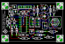
Here is a design of mine from 2006. It's a meter driver circuit using a zero-bias rectifier with separately scaled peak and average reading modes. It takes a 24V power supply, could be scaled down to 12V if needed. The board will be 1.65"x2.6". I haven't built it and tested it yet, just thinking about putting the fab package together and this discussion reminded me.
Attachments
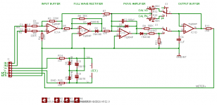
 . Here is the corrected schematic.
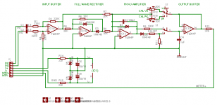
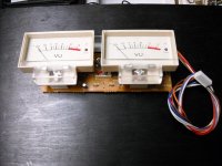
I found the VU meters I had. They are from a TASCAM 112 by TEAC(on PCBs).
It looks like they use a Mitsubishi 5218A Bipolar Op Amp and dual diode rectifier in the circuit with a LED drive for peak detection.
Probably not worth tracing out the circuit, although I have the interface pin-out on paper so I might try them out some time. I think I have 2 or three more stashed some where from when I stripped the tape decks. They all had bad transport mechanisms with bad pinch rollers, and drive pulleys. I was not able to salvage one out of 3 or 4.
Attachments
Well after a bit more testing there is significant distortion with the meter. So the next step would be to build the buffer/amplifier.
But I am also really interested in how this was done in older circuits. Is it as simple as 12ax7 with one side a cathode follower stage and the other an amplifier? If I could make this work with a single tube that would be preferable.
But I am also really interested in how this was done in older circuits. Is it as simple as 12ax7 with one side a cathode follower stage and the other an amplifier? If I could make this work with a single tube that would be preferable.
- Status
- This old topic is closed. If you want to reopen this topic, contact a moderator using the "Report Post" button.
- Home
- Amplifiers
- Tubes / Valves
- dB Meter with tube circuit