Hi all,
I recently found this document:
http://www.triodeel.com/compact.html
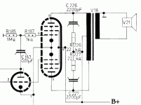
and I'm wondering whether this can be done with EL34. Doesn't it need grid stoppers.. How the balance (drive signal) between the two output tubes. Any comments?
Regards,
Thijs
I recently found this document:
http://www.triodeel.com/compact.html
and I'm wondering whether this can be done with EL34. Doesn't it need grid stoppers.. How the balance (drive signal) between the two output tubes. Any comments?
Regards,
Thijs
tschrama said:...and I'm wondering whether this can be done with EL34. Doesn't it need grid stoppers.. How the balance (drive signal) between the two output tubes.
I don't have a manual in front of me, but I believe EL34's need a lot more grid swing than an EL84 - so your input sensitvity would go way down.
Grid stoppers: you shouldn't need them in this circuit because the gain is so low. This should be very stable.
And I think your last question is: how does it work? Well, read the article - but basically the bottom EL84 is driven from the signal voltage developed across the shared cathode resistor.
I wouldn't call this a "hi-fi" amp, by any means. You see that they don't note the performance in the article.
Joel
Don't see EL34s should not work - the first version of this type of amp I saw was published in Radio Constructor in Feb 1953 and used 6V6s, and I built an amp last year based on the design using 7C5s which works well, as I don't see why the type of output tube matters. I did put a grid stopper to the grid of the first 7C5.
The explanation of why it works, from the Radio Constructor, using its flowery language is:
" When a positive voltage is fed to the first (6BQ5)'s grid, the current through the valve increases, causing a rise in the voltage between it's cathode and HT-. Now the second (6BQ5) is held normally so that it's grid is negative to its cathode by a certain amount, namely the voltage across the (cathode resistor), and any increase in this voltage makes the grid of the second (6BQ5) more negative with respect to it's cathode, so that it's current drops; conversely, when a negative signal causes the first (6BQ5) to lower it's current, the associated drop in voltage across the cathode resistor causes the current in the second (6BQ5) to rise. In other words, push-pull working is the result."
I believe that a similar circuit was discussed on the forum some time ago, but I cannot remember when. A search perhaps?
Found the link - I thought this type of amp had been discussed before:
http://www.diyaudio.com/forums/showthread.php?s=&threadid=9803&highlight=tube+amp
http://www.diyaudio.com/forums/showthread.php?s=&threadid=9803&highlight=tube+amp
Thanks for the replies. I just went ahead and modified my EL34 guitar amplifier. It works fine, and very very little hum! Less than the old circuit.
The output stage was driven by a 12ax7 split-load phase-splitter. This new arangment was very simple to implement, 5 minutes of soldering and done! ). Now I don't need the phase-splitter anymore and it is now available for a high-gain-mod circuit.
I don't think distortion or power output is important in my application (guitar amp). But why wouldn't this topology be HiFi? It could make a nice low-cost amp.
Regards,
Thijs
The output stage was driven by a 12ax7 split-load phase-splitter. This new arangment was very simple to implement, 5 minutes of soldering and done!
I don't think distortion or power output is important in my application (guitar amp). But why wouldn't this topology be HiFi? It could make a nice low-cost amp.
Regards,
Thijs
I've used the configuration with a constant current source as the cathose 'resistor'. The balance is proportional to the value of this resistor so make it as large as possible. As has been commented the EL34 really need more 'umph' to drive them than the 6C4 provides. How about an ECL82 to drive it? Two stages in one bottle. It would make a nice inexpensive PP amp.
I'm designing a low power guitar amp for one of my sons using this output configuration to keep the cost down. He's willing to spend $2500 on a guitar, $250 on speakers but wants the amp for $25... I don't know - the Youth of today...
ciao
James
I'm designing a low power guitar amp for one of my sons using this output configuration to keep the cost down. He's willing to spend $2500 on a guitar, $250 on speakers but wants the amp for $25... I don't know - the Youth of today...
ciao
James
...As regards fidelity, the original article (from which I quoted from before) argued that the the circuit was in class AB, that each of the output tubes must work on the straight part of their curve (in effect, class A), which limited the output power but gives the least distortion...
James, if your son is not prepared to fork out for a decent amp, buy an old transistor radio from a junk shop and run the guitar connecting the leads across the radio's volume control - it will teach him about distortion effects anyway...
James, if your son is not prepared to fork out for a decent amp, buy an old transistor radio from a junk shop and run the guitar connecting the leads across the radio's volume control - it will teach him about distortion effects anyway...
Thanks for the link.
As I understand it, the main dis-advantage is the loss of output power since my EL34 take about -35 Volt bias supply. This voltage must be generated across the bias resistor, so it is subtracted from my HT supply (440Volt)?
Am I corrected when I think I do not loss sensitivity compared to a split-load driven output stage?
How about giving each output tube it's own bias-resistor, and connect the tow bias-resistors with capacitors or a low value resistor (47ohm). Would that improve the Iq balance (no need for tube matching)? Would the 47Ohm (localk degeneration) improve lineairuty by any significance?
Regards,
Thijs
Now were talking!
This is an excellent scheme , I have used this on several breadboard amps and it is a genuine improvement over seperate bypassed resistors or a single resistor . Variable grid bias from a negative supply and a bias meter between cathodes (via 1r resistors) is icing on the cake . Dissipation in the sink is kept down (according to bias supply) , core saturation is eliminated when biased correctly and there is no crossover distortion as the output stage runs in class A . To date I have not found a preferable output stage topology for PP ! Very simple to implement with a depletion mosfet or battery biased IRFxxx
316a
James D. said:I've used the configuration with a constant current source as the cathose 'resistor'.
This is an excellent scheme , I have used this on several breadboard amps and it is a genuine improvement over seperate bypassed resistors or a single resistor . Variable grid bias from a negative supply and a bias meter between cathodes (via 1r resistors) is icing on the cake . Dissipation in the sink is kept down (according to bias supply) , core saturation is eliminated when biased correctly and there is no crossover distortion as the output stage runs in class A . To date I have not found a preferable output stage topology for PP ! Very simple to implement with a depletion mosfet or battery biased IRFxxx
316a
Hi,
Gain's got little or nothing to do with it.
No extra component will ever " improve" the sound if it's not strictly needed so, if you're not suffering from RFI it may be worthwile to leave them out anyway.
RF courses come highly recommended nowadays...
Cheers,
Grid stoppers: you shouldn't need them in this circuit because the gain is so low.
Gain's got little or nothing to do with it.
No extra component will ever " improve" the sound if it's not strictly needed so, if you're not suffering from RFI it may be worthwile to leave them out anyway.
RF courses come highly recommended nowadays...
Cheers,
Fuling said:It´s a shame that the ECLL800 tube is getting very expensive and hard to find, that tube would be excellent for such an amplifier.
Two "power" pentodes (quite similar to 6AQ5/EL90/6V6 if my memory serves) and one driver triode in the same bulb!
I have 4 or 5 of those
dave
Attachments
Hi Planet10,
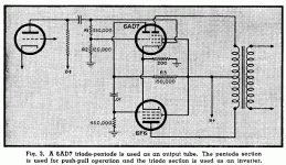
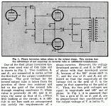
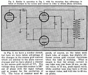
I think I recognize both your last two topologies as describted in the 'Radio Designer's Handbook' by F Langford-Smith (page 585). They are said to have:
'inherent high distortion' and
'serious unbalance between the two input voltages' and
'second harmonic [distortion] [and higher even order] will be the same as a single valve' and
'third harmonic [distortion [and higher odd order?] approximate twice the value'
Doesn't sound nice
Somehow I don't understand why the second order harmonics aren't canceled... any insights from you?
Regards,
Thijs
Hi,
IMO, that's because the output stage isn't nearly balanced enough to have second harmonic distortion cancelled out.
It wouldn't come as a surprise if PSRR is on the low side either...
Nothing that can't be overcome but you'd obviously lose the economic appeal of the design in the process.
Cheers,
Somehow I don't understand why the second order harmonics aren't canceled... any insights from you?
IMO, that's because the output stage isn't nearly balanced enough to have second harmonic distortion cancelled out.
It wouldn't come as a surprise if PSRR is on the low side either...
Nothing that can't be overcome but you'd obviously lose the economic appeal of the design in the process.
Cheers,
- Status
- This old topic is closed. If you want to reopen this topic, contact a moderator using the "Report Post" button.
- Home
- Amplifiers
- Tubes / Valves
- Very simple P-P output stage...will it work?


