Another variant would be to use a thin bobbin of square or rectangular (large dimension) shape and just stack a zillion small snug fitting U-I laminations over it. If one could find "long" U lams with an extra wide bottom to the U, one could skip the I lams, easier to assemble. Or use a bunch of small diam. cut cores fitted over the bobbin like a string of beads with ty-wraps. Could even try the common ferrite cut cores, but it takes like 4 or 5 times as much core area using ferrite as compared to steel. Make it the same overall size as the amplifier chassis and it can fit in that typically unused space around the inside corner/edge of the chassis. Then some set screws tapped into the corners of the chassis could be used to tighten up the lamination stacks to maximize Mu and minimize core vibration.
Last edited:
Smoking-amp!
For example on a PP OPT?
Greets:
Tyimo
Could you explain to me how to do that progressive wind?The ultimate output transformer is also quite easy too make using a toroid winder machine with progressive wind capability. No interleaving required, no magic or mumbo-jumbo OT voodoo, simple as making a peanut butter sandwich. You can set the machine up (typically programmed control), and return when its all done. No labor. Just a single progressive wind layer for each winding across the full core with good insulation between windings.
For example on a PP OPT?
Greets:
Tyimo
Toroid Progressive Winding
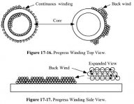
Progressive winding used to decrease layer to layer capacitance. For example: 10 turns forward, 9 turns backward (see picture attached). Another benefit of this kind of winding that it is possible to distribute very smoothly large number of turns in single section.
However, properly designed audio frequency toroids don't need it. In other words, its possible to avoid this increase of complexity without sacrifice of product quality.
Could you explain to me how to do that progressive wind?
For example on a PP OPT?
Progressive winding used to decrease layer to layer capacitance. For example: 10 turns forward, 9 turns backward (see picture attached). Another benefit of this kind of winding that it is possible to distribute very smoothly large number of turns in single section.
However, properly designed audio frequency toroids don't need it. In other words, its possible to avoid this increase of complexity without sacrifice of product quality.
Attachments
R-Core
There is also another ill-fated idea for audio output transformers - R-core.
R-Cores are invented by Kitamura Kiden for power transformers. They built from continuous strip of metal (without gaps), have small circular cross-section area (relative to length/width) optimized for 50/60/400 Hz, and not 20 Hz. Moreover, R-cores have 2-bobbin design, which is not good for audio.
O-Cores. Made by the same non-cut technology as R-cores but shaped as doughnut (O-core looks like toroid but is not toroid !). Suppliers for these cores are scarce, and application. for audio-frequency transformers is very questionable.
Thanks LinuksGuru!Progressive winding used to decrease layer to layer capacitance. For example: 10 turns forward, 9 turns backward (see picture attached). Another benefit of this kind of winding that it is possible to distribute very smoothly large number of turns in single section.
Now I understand it.
Could you tell me what do you mean on "properly designed audio frequency toroids?"However, properly designed audio frequency toroids don't need it.
For example designed and calculated for 20Hz?
Tyimo
Thanks LinuksGuru!
Now I understand it.
Could you tell me what do you mean on "properly designed audio frequency toroids?" For example designed and calculated for 20Hz?
Tyimo
1) Lowest frequency 20 Hz;
2) Leakage inductance <= 20 mH;
3) Ability to sustain +/- 7mA imbalance of output tubes idle current without LF drop at max and low signal level/lowest frequency (20 Hz);
4) Software simulation of transformer behavior and winding layout;
5) Rigorous testing of finished unit in real amplifier circuit (not just generator/oscilloscope).
Last edited:
Thanks!
What about fully symmetric winding for the primaries? Like bifilar winding?
Tyimo
Do you mean balanced or bifilar windings? This is not the same.
Bifilar one made with 2 wires simultaneously, usually in CFB/unity coupled transformers to minimize phase shift and thus, avoiding possible oscillation.
Balanced made on 2 bobbins, or on one bobbin separated in 2 equal segments.
None is required for "standard" audio output transformer with single center-tapped primary and single secondary. Although 2 parts of primary will have slightly different DC resistance (approximately 10% or so, usually 15 - 30 Ohms), this is nothing compared to full primary impedance (several KOhms) and can be neglected.
Still working on the Pi wound output trannys. Its just taking longer than expected due to house moves twice
R-Cores could be used in output trannys. the windings would need to be balanced either side the same as with a single c-core. Obviously they would only work for PP and would not tollerate any curent imbalance. Or they could be used single ended either parafeed or with a winding with DC on, servo controlled to track in opposition the DC in the primary.
R-Cores could be used in output trannys. the windings would need to be balanced either side the same as with a single c-core. Obviously they would only work for PP and would not tollerate any curent imbalance. Or they could be used single ended either parafeed or with a winding with DC on, servo controlled to track in opposition the DC in the primary.
I mean bifilar windings. (made with 2 wires simultaneously)Do you mean balanced or bifilar windings?
Like this here.
________________________________________________________Rick...
This is not exactly a new idea, I believe in 1885 the Ganz factory in Budapest made a transformer like this.
Attachments
Why is SmokingAmp suggesting the progressive winding?Just a single progressive wind layer for each winding across the full core with good insulation between windings.
Is there any reason except to decrease layer to layer capacitance?
Tyimo
Of course there is - it comes down to the voltage difference between particular turns in the winding. Although the turn to turn capacitance is the same, the AC voltage between adjecent turns is generally very small, while the AC voltage between turns across multiple layers can get very large, especially in a toroid. A larger AC voltage makes the apparent capacitance between turns that are adjecent physically but spaced in terms of the amount of winding between them, act as a larger capacitance, proportional to the AC voltage at that point in the winding.
With a toroid, the winding is done across a relatively long length of core, several times that of an equivalent EI. This means that when you make a full circle around the core, and start on the next layer, you normally do that without an insulation layer inbetween, the next layer turns have the same turn-to-turn capacitance to the previous layer, as do adjecent turns in that layer, but the voltage difference can easily be several orders of magnitude higher. The layer to layer capacitance will also behave that way.
However, if you wind progressively, putting the whole winding in one core turn, the AC voltage between each physically adjecent turn is kept low, so the whole distributed capacitance appears much lower (the difference can easily be an order of magnitude).
Keep in mind that this capacitance and the leakage inductance form a resonant circuit, the fo of which you want to keep as far from the audio frequency band as possible.
One of the reasons mains toroids can be used as OPTs is that it's very difficult to wind a toroid for very large leakage inductance. So, even though the distributed capacitgance may be very high, the low leakage inductance usually results in acceptably high resonance frequencies, while the low end is still acceptable compared to the price you pay.
However, a winding machine capable of progressive wind takes exactly the same time and labor to make one, as it takes for a normal winding - so there is a LOT to gain in performance with no additional cost.
There are other pit-falls in toroid OPT design, though. For one, to get acceptable tolerance to DC flux, one can wind for a low flux density, however, the OPT becomes very large and the number of turns increases which increases idistributed capacitance (becoming a problem for the primary windings), plus the total length of wire increases, resulting in substantial DCR of the winding (becoming a serious problem for secondary windings). Adjusting wire sizes and winding styles usually results in non-standard core sizes (usually with a larger opening in the core). Most winders also wind cores from tape lamination, so that is usually not a problem.
Re bifilar windings on a toroid, I will share a recent experience:
The capacitance between two quarters of a PP primary that are wound bifilar, on a 30W OPT (admittedly calculated to go down to 20Hz), is about 65nF. Capacitance between two separately would standrad windings with the same number of turns, separated by the minimum amount of tape insulation is about 2nF. If you want the resosnances of the transformer to be pushed far outside the audio band where you practically do not need to be concerned about them at all, it is obvious what method of winding you have to chose.
Keep in mind that even a half-properly would toroid achieves an order of magnitude less leakage inductance compared to EI cores. This is a very direct manifestation of excellent magnetic coupling between windings, which is generally the reason why bifilary winding is used at all in transformers.
CFB is a special case because the windings can be arranged so that parallel wires only have a higher DC voltage differential, whereas the AC voltage between the wires is very low, in this case bifilar winding is the best you can do, because the capacitance between adjecent wires will not be an issue - dielectric strength of the enamel might be, however. For all other primary windings, bifilar winding on a toroid is not a good idea.
If your aim is to balance the DC resistances of the windings, sectioning is better. It will also reduce parasitic capacitances if the sections are interleaved with parts of the secondary winding, although more than acceptable results can be had just by putting a layer of standard insulating tape between the sections. For PP windings, the number of sections must always be even if DCR balance is the aim - the minimum is 4 sections, one half of each half primary per section. Connect the two outer sections in series to get one half of the primary, and two inner sections to get the other half - the mean turn length is the same this way and the total length of wire in each half-primary will be very close, so the DCR will be balanced.
TIP: grounding the core reduces the parasitic capacitance by a small, but often useful amount.
Please note that progressive winding to lower layer to layer capacitance only tackles one of the capacitive components in a transformer.
The primary by itself also has a capacitive component, the longer the wire the more capacitance.
Therefore choosing a big core with "little" copper is IMHO always better than a small core with "much" copper (apart from nowadays catastrophic copper prices!).
With the big core / little copper combo the lower capacities and DC resistances (copper losses) make better transformers.
quote....One of the reasons mains toroids can be used as OPTs is that it's very difficult to wind a toroid for very large leakage inductance.
Fallacy No1! I've come across some dreadful examples of bunched unequal windings on a toroid with a far worse leakage inductance than an E&I and it's remarkably easy to get it wrong as well as getting it right. The 4 ohm tap is a well known example.
richy
Fallacy No1! I've come across some dreadful examples of bunched unequal windings on a toroid with a far worse leakage inductance than an E&I and it's remarkably easy to get it wrong as well as getting it right. The 4 ohm tap is a well known example.
richy
True, buit you do not get the luxury of a 4-ohm tap when using a mains toroid as an OPT. You must admit that bad winding techniques really are just that - I was refering to a properly made mains toroid. Having dealt with toroid winding machines one on one just recently, it really takes a rather monumental amount of incompetence to set it up so that it's badly wound - yet I do know of a couple of examples myself. It's bad practice which leads to loss of copper, something most winders today don't ignore with copper prices at current levels.
Therefore choosing a big core with "little" copper is IMHO always better than a small core with "much" copper (apart from nowadays catastrophic copper prices!).
With the big core / little copper combo the lower capacities and DC resistances (copper losses) make better transformers.
Having heard some of your transformers i would agree with this
Thanks Ilimzn!
How can wind the whole primary winding (many hundreds of turns) in only one core turn???
I konw that by toroid wind anyway I have to care about to spread the turns around the whole core.
An ideal toroidal coil has its winding spread over 330 degrees of the core. This leaves ca. 30 degrees gap an the ends of the winding.
I thougt that progressive winding is good for sectioning and for perfect splitting the primary.
Like one half of the core is for the half of the primary windings and the another half of the core is for the rest of the primary. 50%-50%.
Could you show me a picture or a drawing to understand it?
Tyimo
I don't understand this.However, if you wind progressively, putting the whole winding in one core turn, the AC voltage between each physically adjecent turn is kept low, so the whole distributed capacitance appears much lower (the difference can easily be an order of magnitude).
How can wind the whole primary winding (many hundreds of turns) in only one core turn???
I konw that by toroid wind anyway I have to care about to spread the turns around the whole core.
An ideal toroidal coil has its winding spread over 330 degrees of the core. This leaves ca. 30 degrees gap an the ends of the winding.
I thougt that progressive winding is good for sectioning and for perfect splitting the primary.
Like one half of the core is for the half of the primary windings and the another half of the core is for the rest of the primary. 50%-50%.
Could you show me a picture or a drawing to understand it?
Tyimo
Last edited:
May be you mean something like this:
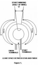
"Progressive Winding:
Divide the total number of turns in two parts (50% each) like in a common mode choke and start to wind following the sequence indicated in figure 1, starting in ‘a’ and following the turns for each side in layers until obtain the total number required, neither start or finish can be in touch each other and the space between they must be maintained by any physical way according to the specified in the IML for the product."
Attachments
- Status
- This old topic is closed. If you want to reopen this topic, contact a moderator using the "Report Post" button.
- Home
- Amplifiers
- Tubes / Valves
- Odd/Crazy output transformer design?