Hello,
I have seen these trannys wound by John Lenard Burnett:
Lenard Audio - Education - Valve Amps
Scroll down to the Pi wound ones.
I have had an idea based on the already existing planar transformers used in switch mode supplies but using pair of iron c-cores.
If I had a load of flexible PCBs made with the windings on either side connected with vias and insulated either side then stacked up P-S-P-S etc. Then connected to form the whole winding for P and S.
This should make a very high bandwidth tranny with almost ideal coupling that could be configured for all sorts eg. UL, CFB etc. The insulation of flexible pcbs is capable of 3KV continuous so no probs with insulation. interlayer capacitance could be problem though. Thicker insulation?
What do you guys think? Is it feasable? I know it would be expensive for one or two but for lots it would be minimal. The transformers could be considered identical due to the high tolerance of production and the balance for a push pull tranny would be perfect.
A bit like this:
http://archive.electronicdesign.com/files/29/7647/figure_02.gif
Cheers Matt.
I believe I have seen a patent using the same idea. Try a patent search online for audio output transformer. I'm not aware of anyone using this to construct transformers though. Patent might be expired too. Seems likely that you would end up with too much insulation and not enough copper in such a setup, and an enormous connectivity problem between all the layers.
The ultimate output transformer is also quite easy too make using a toroid winder machine with progressive wind capability. No interleaving required, no magic or mumbo-jumbo OT voodoo, simple as making a peanut butter sandwich. You can set the machine up (typically programmed control), and return when its all done. No labor. Just a single progressive wind layer for each winding across the full core with good insulation between windings. (well, one does have to change the wire spools and insulation spools on the winder between the windings) If you are concerned about DC balance with a toroid core, all that is required is a thin film coating on the steel lamination before its wound up into the toroid form to make a distributed gap. (the flux has to cross between lamination layers)
A SE design can be made using a thicker separator film.
All those audio OT winders out there just have the wrong stuff. And they're stuck with paying it off. But make sure you don't buy a toroid OT wound using random wind technique. Those old winder machines were used for 60 Hz power xfmrs, and will make a rotten audio OT.
Last edited:
Thanks for the great reply Smoking Amp.
I did a patent search and cant find any use in audio. You may have better access in the US for this.
I completely agree that connecting each layer is a pain. I have worked a way around this in design only
You would be supprised on the amount of copper that can be stuffed in. I have done a fair amount of research before posting ie. finding out whats available and designing layers etc.
I reckon and this is by no means spot on that approx 10-15% more copper can be used compared to a normal output tranny. Of course this is based on the usual 3mm margins to the core. I started with a track width rated for 300mA in a six layer board ie. buried. My first design barely filled 40% of the window and this was derated to account for the current etc. This is for a 3K3 ppp 807 type design.
Torroid output trannys are not ideal no matter how they are wound. Sorry to be pessimistic about this but its true. I have heard/read rumors of a distributed gap in the Plitron/Van Der Veen types but I dont believe it. Perhaps George could give comments on his 400W trannys and their ability to take out of balance tube currents.
I have also used a pair of admittedly mains torroids in a 6080 amp very much along the lines of Shoog. I found them to be very perculier about DC offset in PP. With CCS forcing class A they sound great. For SE forget it. Apparently there are makers of SE torroid transformers, perhaps they have some crazy LASER that can cut it so fine
Not that I care too much for SE. A pair of GM-70 would be OK by me
My idea is to address all these problems. With a C or EI core it is rellatively easy to arange a gap. This has advantages in PP as well as SE. Especially with the more modern cores where a lowering of permiability is not as bad as with a non GOSS core. Clearly an EI core cant take advantage of this but the simplicity in production may well win it.
You hint at insulation and capacitive problems. This is the only downfall I can see. And as the first design, even though it was derated only filled 40% I dont see it as a problem.
Please guys especially Bud. P. Come in on this as I need to be shot down in flames
Cheers Matt.
I don't think you can create a distributed gap by spacing a closed tape core. The physics of it doesn't make sense, and if it worked you'd probably see it a lot, which I personally haven't. Got equations?
I'm finding it hard to imagine getting enough turns on a planar transformer to be useful with anything but something like a bunch of 6C33C or some inverted grid experiement.
I'm finding it hard to imagine getting enough turns on a planar transformer to be useful with anything but something like a bunch of 6C33C or some inverted grid experiement.
For a tape wound core, the flux has to jump from layer to layer to form closed loops. The gap then consists of the spacing between lam layers, but with the whole turn as length by the tape width (very large gap area). The whole turn acts as a lot of conventional gap in parallel (just like resistors in parallel), so its hard to get much equivalent gap without putting in a fair amount of spacer. This can cause your steel cross-sectional area to suffer with all that spacer in there (so requiring more turns or a bigger core). So its more effective to just cut a gap in the core in one place (a saw) for SE cores where a larger gap is required. Its always done that way for SE type cores for practical purposes.
However, the distributed gap approach does not suffer from the field radiating out from a localized gap, making it less of a shielding problem. And P-P does not require much spacer to bring it in line (effective Mu) with the butt joint gaps of E-I. The formulas are quite simple: effective gap = spacer width * ( tape cross section area)/(turn length*tape width) You can see that the last (...)/(...) terms are a very small fraction, leading to the high effective permeability of non spacered toroids.
In any case, I don't think that Plitron has any effective gap in their P-P cores unless they have come out with something new. (A cut gap would be too large for P-P fixup) Without some gap, you have to contend with the critical DC balance.
It has also been remarked that the very large inductance of typical ungapped toroid P-P OTs makes for a lack of tube sound due to the lack of magnetizing current distortion at low frequencies. A distributed gap would fix this. (Well, assuming someone actually wanted to "fix" that "problem". Some, maybe many, would argue that large inductance and low distortion are virtues)
------------------------------------------------
A planar printed circuit transformer would need some vacuum impregnation with epoxy or something to improve the HV insulation properties for tube usage.
OH, I think I have also seen a patent on winding multiple windings on an xfmr using printed flat ribbon cable the width of the bobbin, just coiled up.They just interconnect the wire ends to get the turns ratio. Would have a lot of distributed capacitance maybe if they tried any sectioning/interleaving within the ribbon.
Last edited:
I have had an idea based on the already existing planar transformers used in switch mode supplies but using pair of iron c-cores.
If I had a load of flexible PCBs made with the windings on either side connected with vias and insulated either side then stacked up P-S-P-S etc. Then connected to form the whole winding for P and S.
I think it is possible to make OPT using same technique as used in Planner transformers. You are right you have to make a thick stack of flex PCBs and EI or C core made of silicon steel can be used in same way the ferrite core is used in smaller planner transformer which are made for SMPS.
regards
Hello,
I have had an idea based on the already existing planar transformers used in switch mode supplies but using pair of iron c-cores.
If I had a load of flexible PCBs made with the windings on either side connected with vias and insulated either side then stacked up P-S-P-S etc. Then connected to form the whole winding for P and S.
Cheers Matt.
Your idea is good I think it is possible to make OPT using same technique as used in Planner transformers. You are right you have to make a thick stack of flex PCBs and EI or C core made of silicon steel can be used in same way the ferrite core is used in smaller planner transformer which are made for SMPS.
regards
The ultimate output transformer is also quite easy too make using a toroid winder machine with progressive wind capability. No interleaving required, no magic or mumbo-jumbo OT voodoo, simple as making a peanut butter sandwich.
Unfortunately, interleaving IS required, albeit not so much interleaved sections between primary/secondary required (compared to EI/double C core).
Currently I have 2 over-sized 70W audio toroids with leakage inductance only 17 mH.
Additionally, toroid must have unusually large internal diameter in order to accommodate several layers of primary/secondary connected in parallel (on main, secondary is wound with wire d = 1.4 mm).
Sorry guys been working away again
This seems to be going the way of toroids which was not my intention, merely a reply to Smoking Amp.
Yes torroids work but that was not the point of my OP.
I agree that each layer would need to be stuck together to stop any audible ringing. The HV qualitys of flexible PCB are such that 1 though (your mill) will withstand 3KV.
Cheers Matt.
This seems to be going the way of toroids which was not my intention, merely a reply to Smoking Amp.
Yes torroids work but that was not the point of my OP.
A planar printed circuit transformer would need some vacuum impregnation with epoxy or something to improve the HV insulation properties for tube usage
I agree that each layer would need to be stuck together to stop any audible ringing. The HV qualitys of flexible PCB are such that 1 though (your mill) will withstand 3KV.
Cheers Matt.
I enjoyed reading the Lenard Audio page, but found a horrible glaring error on page 4:
Cathode bias is described as Class A. Using 2 output valves is described as push pull. Therefore 2 output valves that are Cathode biased is described as Class A push pull.
Experimental TX
I always thought EI, Toroids, Cs'...et. al. ....were oriented too much to mass production, with little thought toward optimal performance.
Taking into consideration the three dimensional shape of the magnetic fields generated, one could come up with a superior design of laminations.
Myself, I thought, a roughly apple shaped arrangement of concentric laminations would work optimally.
I do believe when someone out there stumbles upon a core shape/composition...winding of bizarre conductor/insulator materials the EI will go the way of the Horse & Buggy.
_____________________________________________________Rick......
Cost vs performance.
Damn bean counters always win.
Look at E core/ I core lamination's and they are "Loss-Less". You get two Es and two I's from one rectangular section. Allign it properly and you minimize material loss and maximize profit.
So spins the world.
Damn bean counters always win.
Look at E core/ I core lamination's and they are "Loss-Less". You get two Es and two I's from one rectangular section. Allign it properly and you minimize material loss and maximize profit.
So spins the world.
Last edited:
Sorry guys been working away again
This seems to be going the way of toroids which was not my intention, merely a reply to Smoking Amp.
Yes torroids work but that was not the point of my OP.
I agree that each layer would need to be stuck together to stop any audible ringing. The HV qualitys of flexible PCB are such that 1 though (your mill) will withstand 3KV.
Cheers Matt.
I'm not sure that sticking the "windings" together is that critical; any ringing or vibration in an OPT would be due to magnetostriction in the core. I'm fascinated by your idea. What kind of fill density have you been able to calculate? At first glance using a sort of "edgewound" coil appears to have some advantages in terms of coupling.
John
The apple shape does indeed look ideal. I have heard/read that some input trannys were made by Tellefunken this way. Any German readers to confirm?
I am under way now winding some transformers using the Pi arrangement. I have worked a way to make it fairly easy using normal methods, if extremely labour intsensive.
I did think to start that the multi-layer PCB approach would be easy. It is not. I have found a way over the inter-conection problems but it is by no means trivial.
Using normal winding methods, Crowhurst hints at some handy tricks. If the bobbin consisted of a load of sections Ie sectioned vertically a fair few times. Then each section could be wound in segments and the start of each winding reversed. Pretty hard to explain. The paper is called Output transformer Design.
I plan to make this pair of trannys and compare them to a pair using the same core cross section and of fairly standard construction. The only reasoning behind this is because I would like to see if there really is an advantage and if it is worth me persuing the PCB design as this is extremely expensive as a prototype.
Anyway, can anyone point me to a good high voltage, low output impedence amplifier design? I remember Elektor doing one a while back.
Cheers Matt.
Hello,
I have seen these trannys wound by John Lenard Burnett:
Lenard Audio - Education - Valve Amps
Scroll down to the Pi wound ones.
I have had an idea based on the already existing planar transformers used in switch mode supplies but using pair of iron c-cores.
If I had a load of flexible PCBs made with the windings on either side connected with vias and insulated either side then stacked up P-S-P-S etc. Then connected to form the whole winding for P and S.
This should make a very high bandwidth tranny with almost ideal coupling that could be configured for all sorts eg. UL, CFB etc. The insulation of flexible pcbs is capable of 3KV continuous so no probs with insulation. interlayer capacitance could be problem though. Thicker insulation?
What do you guys think? Is it feasable? I know it would be expensive for one or two but for lots it would be minimal. The transformers could be considered identical due to the high tolerance of production and the balance for a push pull tranny would be perfect.
A bit like this:
http://archive.electronicdesign.com/files/29/7647/figure_02.gif
Cheers Matt.
That's a blast from the past.
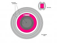
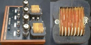
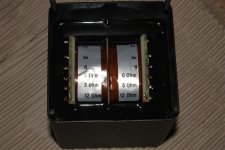
I believe the first Pi OP trannies for Lenard Audio were wound by Alkay
Transformers - I was working there when we did them.
They were pretty difficult to wind. Every one of those sections was, from
memory, done separately and then they were stacked together with nomex
insulation between them.
The whole idea of Pi winding is to reduce the layer to layer voltage gradient
and distributed capacitance. With this style of winding there is much lower
paralleled winding capacitance so end result is greater bandwidth -
theoretically.
The amps were, fom memory open loop KT88 push pull.
cheers
Terry
Attachments
Looking at Richard's "apple" shaped xfmr above (a standard ferrite pot core essentially), I am reminded of a discussion on DIY recently where this setup was inverted to become an inverted toroid xfmr with wire forming the toroid "core" and lamination strip or steel wire forming the "winding" on the outside. Very easy to wind the copper at least. Would use a very large diameter bobbin of small cross section ( a small wire winding window), maybe 8 or 10 inch major diameter.
This could be modified to a stack of large diameter/ thin cross section Pi wound coils (say primary 1, sec., pri 2) Then the magnetic material gets wound over the bobbin set to maybe a 1/4 inch depth using a toroid winder. A conventional toroid winder would work for steel wire at least. These winders also have a special shuttle for winding insulating (thin mylar etc) tape on a toroid, but unfortunately they sharply bend the tape during its removal from the shuttle. This would have to be re-worked for steel tape. Magnetic tape would have the advantage of grain orientation available, never heard of grain oriented wire though. Could even use permalloy tape, readily available.
As any transformer winder knows, the balance between copper and steel can be tipped either way. With copper so expensive lately, tipping to more iron makes good economic sense, and less turns of copper means less winding resistance. Looking at the inducatance formula, the lower turns has to be offset by larger core area AND lower magnetic path length. This is exactly the forte of this method. (if you work out all the formulas, you will find that the two methods (this versus traditional) can give equivalent results for equivalent materials) Reducing the usual 2000 to 3000 turn primary wind down to 100s of turns certainly has to be attractive for DIY also. Although the toroid winder machine will still have to wind 1000s of "turns" of steel wire or tape. A bobbin with a round cross section bottom and a rounded wire pile-up on top could optimize the magnetic path length further.
Should probably check with Kenpeter to see if he has wound one of these already on a plastic bicycle rim "bobbin" (copper magnet wire in the rim) with enamel insulated steel bailing wire wound over the outside.
Last edited:
- Status
- This old topic is closed. If you want to reopen this topic, contact a moderator using the "Report Post" button.
- Home
- Amplifiers
- Tubes / Valves
- Odd/Crazy output transformer design?