Being a tube newbie, I have no information to pull from. I just see some of these pull in exscess of $200 per tube while others run less than $100 per pair. So, somebody thinks there is a difference. I'm just trying to find out which are considered better and why.
I'm in the market for a set of 2A3 for a direct coupled 2A3 amp I'm building. I realize there is a large gap between a 1943 RCA single plate and a 2003 TJ Mesh. I'm soaking it all in like a sponge.
I'm in the market for a set of 2A3 for a direct coupled 2A3 amp I'm building. I realize there is a large gap between a 1943 RCA single plate and a 2003 TJ Mesh. I'm soaking it all in like a sponge.
Wardsweb said:Being a tube newbie, I have no information to pull from. I just see some of these pull in excess of $200 per tube while others run less than $100 per pair. So, somebody thinks there is a difference.
Yes, and they probably have as much info as you do. Don't let price alone dictate your tube purchases. By that logic the best sounding amp would be made entirely of circa 1916 "audion" tubes, with voltage gains of 2, and 29% distortion.
")
IMO, no tube out there has specifications worth $200.
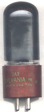
2A3
Hi,
It seems that the general consensus amongs die hard tubelovers is that the single plate versions are the ones to go for.
If you can still find some that is. Most of what passed through my hands ended up in Japan and Taiwan where they seem to be highly sought after.
I sold a pair of 2A3Ws (593x? something) recently and compared to what came standard with that particular amp, they sounded much better according to the customer.
If they're worth the extra expense is up to you of course.
So, it seems you're going to build yourself a Loftin-White, have you decided wat to use for the input yet?
Cheers,
Attachments
Joel - I know dollars will not be the deciding factor. I just wanted some input as to what people thing about these tubes versus buying some newer stuff, which would add a whole new level to the matrix of options.
fdegrove - Input via 6SL7 with a 5AR4/GZ34 for rectification.
fdegrove - Input via 6SL7 with a 5AR4/GZ34 for rectification.
Hi,
Something along these lines?
Cheers,
Input via 6SL7 with a 5AR4/GZ34 for rectification
Something along these lines?
Cheers,
Attachments

Input via 6SL7 with a 5AR4/GZ34 for rectification.
Sounds similar to the amp I just built. Mine is the JE Labs/Angela design, with an SRPP 6SL7 driver stage. Here's the 8-page thread on it:
http://www.diyaudio.com/forums/showthread.php?s=&threadid=16246
I used Sovtek 2A3s, about $70 for a matched pair from www.triodeelectronics.com. I'm pretty happy with the sound of this amp, but of course I haven't tried any other 2A3s in it. The Sovtek's usually get favorable comments for being good inexpensive 2A3s. Apparently, they are also capable of higher power dissipation than some NOS 2A3s. I know the design I built runs them hotter than 15W. People have used the Sovtek tubes in this design for a year with no reported problems. I remember reading somewhere that NOS single plate RCA 2A3s are more "fragile", and shouldn't be run higher than 15W. I have no idea if that statement is accurate or not.
Why not use a 12AY7 with a 6SJ7 pentode as its plate load?
That would cost too much.
Cheers,
fdegrove said:...That would cost too much.
Actually, you can pick up both NOS together for under $10 US. There isn't a whole lot of demand for 6SJ7's.
And if you need less gain, another combination that works is a 6AG5 as the plate load for a 6J5. They both draw 8mA. Also both cheap tubes, relatively speaking.
cheers
Joel,
Wasn't I just pulling your leg?
The SRPP is similar anyway and the SL7 is known to do well there.
Another plus is that it doesn't use much real estate.
Cheers,
Actually, you can pick up both NOS together for under $10 US.
Wasn't I just pulling your leg?
The SRPP is similar anyway and the SL7 is known to do well there.
Another plus is that it doesn't use much real estate.
Cheers,
Frank, questions about the schematic you posted. I had considered building that too, but ended up going with the JE Labs one because it was just slightly simpler (lower B+ voltage, and marginally simpler way of raising the DC voltage of the 6SL7 heater). Anyway...
* What is the "Neon Pi..." connected across the PS transformer's primary winding? Electronically it's an R and a C, the oval around it probably indicates that those are within a single package. Physically, what does it look like, and what's the complete name of this component?
* Is it advisable to put the power switch on one leg of the transformer and the fuse on the other? I always thought that it was better to put both the fuse and the power switch on the "live" leg, with the fuse coming first. Maybe if the wall supply has both legs being hot and inverted w.r.t. each other (like we have in India), then it's irrelevant where the switch and fuse go.
Hi,
Soneone picked an odd symbol for that one, it's just a filamentary on/off indicator, you know those that work straight form the 117VAC supplies...
It's not critical anyway...
Some Power companies change polarity randomly so technically it shouldn't matter, if you want to get the best from the amps just check for lowest leakage with a voltmeter and reverse polarity accordingly.
The reason they did it this way, IMHO, is to avoid putting the series R of the switch and fuse on one xformer leg.
Other than that I wouldn't know.
And make that just a guess...
Cheers,
* What is the "Neon Pi..." connected across the PS transformer's primary winding? Electronically it's an R and a C, the oval around it probably indicates that those are within a single package. Physically, what does it look like, and what's the complete name of this component?
Soneone picked an odd symbol for that one, it's just a filamentary on/off indicator, you know those that work straight form the 117VAC supplies...
It's not critical anyway...
Maybe if the wall supply has both legs being hot and inverted w.r.t. each other (like we have in India), then it's irrelevant where the switch and fuse go.
Some Power companies change polarity randomly so technically it shouldn't matter, if you want to get the best from the amps just check for lowest leakage with a voltmeter and reverse polarity accordingly.
The reason they did it this way, IMHO, is to avoid putting the series R of the switch and fuse on one xformer leg.
Other than that I wouldn't know.
And make that just a guess...
Cheers,
And it's always irrelevant which primary leg they are on. It's a circuit afterall.
But if the fuse is on the neutral leg and it blows, the rest of the circuitry would still be connected to the live leg, and could give someone a shock if they accidentally touched it something. If, on the other hand, the fuse is on the live leg, when it blows it disconnects all downstream circuitry. At least, that's the reasoning I've read for putting fuses on the live leg where possible.
Neon pilot light.
Thanks. So it's not a filter of some sort. That's what I thought it was, seeing the R and C symbols in there. Or will a pilot light automatically act as a filter?
if you want to get the best from the amps just check for lowest leakage with a voltmeter and reverse polarity accordingly.
Could you explain that in a little more detail please? Leakage from where to where? What voltages should I measure, exactly, and what connection(s) should I reverse?
Thanks,
Saurav
Hi,
Sorry, open circuit is open circuit.
It doesn't matter where you put it, live or neutral.Those are just conventions anyway.
If it did, I'd put a X-mass tree there lighting there...too bad it doesn't.
According to mains polarity a circuit will leak more or less current.
For best sonic results we want it to leak as little as possible.
To measure leakage current you need a voltmeter set to mA and measure between the amp chassis and earth (real earth is fine, such as a waterpipe, radiator...anything you know to be earthed).
Jot down what you measure, swap the powerchords polarity around ( not always easy to do, so you may need a cheater plug cicrumventing the earth pin), measure again and jot down the results.
The one with the lowest reading is the one to go for.
Do this with nothing else connected on that powerline or the results may be false.
In practice, just unplug everything sitting on that line.
If you do this for everything that you have hooked up in the audio system you'll definetely hear an improvement IMO.
Cheers,
But if the fuse is on the neutral leg and it blows, the rest of the circuitry would still be connected to the live leg, and could give someone a shock if they accidentally touched it something.
Sorry, open circuit is open circuit.
It doesn't matter where you put it, live or neutral.Those are just conventions anyway.
Or will a pilot light automatically act as a filter?
If it did, I'd put a X-mass tree there lighting there...too bad it doesn't.
Leakage from where to where? What voltages should I measure, exactly, and what connection(s) should I reverse?
According to mains polarity a circuit will leak more or less current.
For best sonic results we want it to leak as little as possible.
To measure leakage current you need a voltmeter set to mA and measure between the amp chassis and earth (real earth is fine, such as a waterpipe, radiator...anything you know to be earthed).
Jot down what you measure, swap the powerchords polarity around ( not always easy to do, so you may need a cheater plug cicrumventing the earth pin), measure again and jot down the results.
The one with the lowest reading is the one to go for.
Do this with nothing else connected on that powerline or the results may be false.
In practice, just unplug everything sitting on that line.
If you do this for everything that you have hooked up in the audio system you'll definetely hear an improvement IMO.
Cheers,
Here is my amp build page with the schematic:
http://wardsweb.org/audio/dc2a3.html
and my preamp for good measure:
http://www.wardsweb.org/audio/foreplay.html
http://wardsweb.org/audio/dc2a3.html
and my preamp for good measure:
http://www.wardsweb.org/audio/foreplay.html
Sorry, open circuit is open circuit.
It doesn't matter where you put it, live or neutral.Those are just conventions anyway.
OK, I don't get this. Here in the US, one of the legs measures 120V to earth (the middle pin), while the other leg measures 0V to earth. If I put the fuse in the 0V leg and it blows, the other leg is still connected to 120V. So, if I happened to touch the transformer primary leads, I would be the path for 120V to earth. On the other hand, if the fuse is on the 120V leg and it blows, the transformer primary is now connected to the leg that's 0V w.r.t. earth, so if I touch it I won't be electrocuted.
What am I missing here?
To measure leakage current you need a voltmeter set to mA and measure between the amp chassis and earth
My amp chassis is connected to the 3rd prong of the power plug. Would I have to disconnect that to take this reading? I can't think of any easily accessible radiators or water pipes near my living room. Or should the chassis not be connected to the earth pin?
Also, swapping the power cord should be equivalent to swapping the connections on the power transformer's primary, right?
If you do this for everything that you have hooked up in the audio system you'll definetely hear an improvement IMO.
I'll keep that in mind. Since almost all active components in my system are DIY, this won't be very hard to do.
Thanks,
Saurav
Saurav,
The polarization you are measuring is certainly not a standard. And even if what you were saying was true, it would only be a guess which leg will be hot. It's also a big assumption that the electrician who wired the house gave a rat's *** about polarization.
Anyway, if you only hook the "hot" lead up to your amp, you will not in any way be able to run the amp. Try it.
- Status
- This old topic is closed. If you want to reopen this topic, contact a moderator using the "Report Post" button.
- Home
- Amplifiers
- Tubes / Valves
- Which RCA 2A3 to buy?