Hi there,
I'm completely new to tubes really but have been reading a bit and thought I'd attempt to build a guitar amplifier using salvaged parts from an amplifier that my flatmate bought from a garage sale. It was a stereo amp (Fountain, NZ's finest) but has had one output transformer removed. The remaining output transformer is very bulky (good thing?) so I'm trying to identify which lead is which but using Morgan Jones' method the numbers do not crunch. It has a total of 10 leads, 4 on one side and 6 on the other (not necessarily primary and secondary I guess). I'm fairly certain it's a push pull due to the amp topology and number of leads. The impedances are as follows:
Six wire side -
Brown/orange = 4.4R
Brown/green = 2.2R
Orange/green = 2.2R
Blue/yellow = 1R
Blue/black = 1.4R
Black/yellow = 1.6R
Four wire side -
Blue/red = 172R
Black/yellow = 153.9R
All other impedances measure infinite on my multimeter (cheap POS which measures 0.1-0.5 when leads are connected together anyway). You would think that maybe green is center tap with orange and brown being the anodes but the impedances are far too low. Anyone have any ideas?
Images of trans:
ImageShack Album - 2 images
Attachments
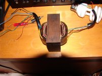
To me it looks like there are 5 wires on one side,with 6 on the other. The higher resistance windings will be the primary,and the low resistance windings will be the secondary/secondaries.
It would seem that the side with 5 wires is the primary,complete with UL taps..But that's only an assumption on my part.
Edit: Nope,there are only 4 wires...The shadow underneath looked like a 5th wire. My bad!
It would seem that the side with 5 wires is the primary,complete with UL taps..But that's only an assumption on my part.
Edit: Nope,there are only 4 wires...The shadow underneath looked like a 5th wire. My bad!
1: Interleaved E-I core = no airgap so it is probably a PP transformer.
2: Oddball resistances, perhaps the primary is indeed asymmetrical ?
3: Grab any mains transformer with reasonably low (= safe) output voltage (say 12-48V), hook it up to mains, measure secondary voltage, feed secondary into one halfprimary of the OPT (say blue-red wires), connect one wire (say black) of the other halfprimary to either end the first one (say blue), then measure voltage across the remaining two wires (red-yellow). If you're reading close to 0V rather than what the output of mains transformer times 2, reverse the black and yellow wires. Measure voltage across outermost wires (now red-black) again to confirm that you're getting roughly twice the output of mains transformer. You have identified the primary taps, outermost wires go to tube anodes, the inner pair is connected together and goes to B+.
Note that you can also hook it up to mains directly if you don't have a suitable mains transformer handy and you feel confident you won't get electricuted in the process.
4: Now hook up your mains transformer output so that it is connected to two outermost wires of the OPT primary, as determined in previous step. Measure voltage across full secondary (brown-orange). Note the value and calculate impedance ratio:
Vin = mains transformer output voltage as measured in step 3
Vout = OPT full secondary as measured in step 4
Zratio = (Vin/Vout)^2
For example, if Vin = 15V and Vout = 0.6V then Zratio = 625
5: Repeat step #4 for all OPT secondary wire pairs that show different resistance to determine all avaliable Zratios. This will allow you to pick the winding that is most suitable to your purpose, considering your nominal speaker impedance. Note that secondary windings can be connected in various ways to get even more Zratios.
Last edited:

This would be Zaa of 5900R : 8R, add DC resistance and you get approx. 6K combined load. Now you can select output tubes and design the circuit around the transformer to fit it best. Depending on transformer dimensions I think you'll be looking at 6L6 or similar tubes - you can always go for lower Zratio with different secondary taps and you should check them out so you can plan accordingly.
A very interesting tube choice would IMO be PCL805, a noval package TV vertical deflection pentode (with triode conveniently enclosed in same bulb) that rarely gets used for audio and which can usually be had for peanuts, you can also buy NOS Russian versions of this tube with 6.3V heaters (= equivalent of ECL805). Unusually high current for such a small tube, a pair of these would probably be on par output power-wise with a pair of 6L6. On top of everything you only need two of these and a fistful of passive components to make a complete PP stage as you only need 20V peak-to-peak to drive the pentodes to both extremes in class AB1 and triode section has mu of ~60 so it can easily cater to required gain of ~20x in either arrangement of the two triodes (if it was me I'd give LTP input over common cathode + cathodyne stage a try for starters).
A very interesting tube choice would IMO be PCL805, a noval package TV vertical deflection pentode (with triode conveniently enclosed in same bulb) that rarely gets used for audio and which can usually be had for peanuts, you can also buy NOS Russian versions of this tube with 6.3V heaters (= equivalent of ECL805). Unusually high current for such a small tube, a pair of these would probably be on par output power-wise with a pair of 6L6. On top of everything you only need two of these and a fistful of passive components to make a complete PP stage as you only need 20V peak-to-peak to drive the pentodes to both extremes in class AB1 and triode section has mu of ~60 so it can easily cater to required gain of ~20x in either arrangement of the two triodes (if it was me I'd give LTP input over common cathode + cathodyne stage a try for starters).
Last edited:
Aah OK thanks for the advice. I was planning on using the other salvaged parts from this amp in order to build a guitar amp. The tubes I have are 4x RCA 7189 (basically an EL84 according to wikipedia), 3x 12AX7/ECC83 and 2x 6AN8A. The power transformer is 350-0-350 with 6.3V heater secondary. I was thinking of a Vox AC30 clone but I'm not sure at this stage. There are tonnes of schematics here for this amp and many others.
This might work as well, two tubes per side and one of the lower Zratio taps. For guitar amp you're going to need extra amplification, above suggestion was meant for audio (lin) input.
Tubes are cheap though, sockets usually cost at least as much as cheapo tubes, potentiometers can be expensive and so can be large capacitors, so this is the largest fraction of the cost once all transformers have been taken care of.
Tubes are cheap though, sockets usually cost at least as much as cheapo tubes, potentiometers can be expensive and so can be large capacitors, so this is the largest fraction of the cost once all transformers have been taken care of.
- Status
- This old topic is closed. If you want to reopen this topic, contact a moderator using the "Report Post" button.
- Home
- Amplifiers
- Tubes / Valves
- Identification of unknown output transformer