Hi again...
Here are some squiggles I drew:
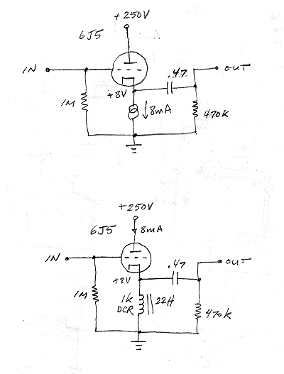
I was thinking that if a CCS was a good thing as the load for a cathode follower, then a choke should be too.
I know the choke pictured above doesn't have much inductance (22H). Is that still a problem considering the very low output Z of a CF?
--
I know a choke isn't as good a load as a CCS, and will have bandwidth limitations a CCS might not, but my question is meant more for my learning/understanding than for building the best possible circuit.
Here are some squiggles I drew:
I was thinking that if a CCS was a good thing as the load for a cathode follower, then a choke should be too.
I know the choke pictured above doesn't have much inductance (22H). Is that still a problem considering the very low output Z of a CF?
--
I know a choke isn't as good a load as a CCS, and will have bandwidth limitations a CCS might not, but my question is meant more for my learning/understanding than for building the best possible circuit.
I was thinking that if a CCS was a good thing as the load for a cathode follower, then a choke should be too.
I know the choke pictured above doesn't have much inductance (22H). Is that still a problem considering the very low output Z of a CF?
For any cathode follower, the larger the tail load, the better. 22H corresponds to: Xl= 2K77 at f= 20Hz. You'd ideally be best off with an r(k)= 276R, which would mean a g(m)= 3.62mA/V, or better. This isn't so difficult to pull off, and so the choke load will work just fine. (Assuming it's a decent choke designed for the purpose and not something like a PS ripple choke.)
I know a choke isn't as good a load as a CCS, and will have bandwidth limitations a CCS might not, but my question is meant more for my learning/understanding than for building the best possible circuit.
Asking is the first step to learning.
Your theory is correct, a choke can replace a CCS - but only under certain conditions. But neither circuit is much good as drawn, as both will very easily overload with any sort of signal level. The cathode of a CF should sit well above gnd, ideally around half the B+ rail to allow maximum voltage swing before any clipping, up or down. This means the grid of the CF needs to be elevated to the same voltage, and the cathode impedance adjusted to suit. Note that a choke will not work with near half the B+ across it...something will smoke.
Regards, Allen
Regards, Allen
Your theory is correct, a choke can replace a CCS - but only under certain conditions. But neither circuit is much good as drawn, as both will very easily overload with any sort of signal level. The cathode of a CF should sit well above gnd, ideally around half the B+ rail to allow maximum voltage swing before any clipping, up or down. This means the grid of the CF needs to be elevated to the same voltage, and the cathode impedance adjusted to suit. Note that a choke will not work with near half the B+ across it...something will smoke.
A choke does not need to. It may sit at zero (ideally) DC, and swing way below zero.
In case of CCS load it should sit at (B+ - Vs)/2
where Vs is a saturation voltage on the max current.
In case of resistor load it should sit at (B+ - Vs)*3/4
A choke does not need to. It may sit at zero (ideally) DC, and swing way below zero.

I'm glad somebody is thinking outside of the sand box.
Last edited:
A choke does not need to. It may sit at zero (ideally) DC, and swing way below zero.
In case of CCS load it should sit at (B+ - Vs)/2
where Vs is a saturation voltage on the max current.
In case of resistor load it should sit at (B+ - Vs)*3/4
1/ This may be all correct, but it's really splitting hairs. The OP had some basic questions, he doesn't need or want a learned maths lession.
2/ The schema the OP drew shows a choke in a zero biased triode CF. Assuming the choke has enough DCR to act as a suitable cathode bias R, it will still have VERY limited output swing, and make massive 2nd harmonic distortion before clipping.
Regards, Allen
1/ This may be all correct, but it's really splitting hairs. The OP had some basic questions, he doesn't need or want a learned maths lession.
2/ The schema the OP drew shows a choke in a zero biased triode CF. Assuming the choke has enough DCR to act as a suitable cathode bias R, it will still have VERY limited output swing, and make massive 2nd harmonic distortion before clipping.
Unfortunately without some math your "very" and "massive" are undefined.
Triode CF is not ZERO biased. It is biased up to the current needed for a maximum of a negative voltage swing on a given output load. Second harmonic distortions will be way below what you may get from an identical common cathode stage with choke loaded anode.
Edit: you may search for Altec 1570 schemo.
Last edited:
I'm glad somebody is thinking outside of the sand box.
Thank you. I'm not so old to forget physics' basics I learned 40 years ago.

A little controversy!
With a DCR of about 1k ohms, that simple resistance with 8mA through it should raise the cathode to +8V, right? That should give us the necessary grid bias, right? Not enough of a load, but then you add...
...The inductance of the choke, which will resist changes in current, creating an AC load that causes a signal voltage swing across the resistance... I think.
Being a buffer with a grid bias of +8V, wouldn't a stage like this CF be used to match a previous high-Z gain stage (amplifying a 500mV signal to let's say 2Vrms) to a subsequent stage requiring a lower Z? So an 8V grid bias would be plenty in that application, right?
That little bit of math I can do. Only thing is, what defines Vs? In the CF with choke in the cathode, the bias is +8V, is Vs = 8V?
--
--
2/ The schema the OP drew shows a choke in a zero biased triode CF. Assuming the choke has enough DCR to act as a suitable cathode bias R, it will still have VERY limited output swing, and make massive 2nd harmonic distortion before clipping.
With a DCR of about 1k ohms, that simple resistance with 8mA through it should raise the cathode to +8V, right? That should give us the necessary grid bias, right? Not enough of a load, but then you add...
...The inductance of the choke, which will resist changes in current, creating an AC load that causes a signal voltage swing across the resistance... I think.
Being a buffer with a grid bias of +8V, wouldn't a stage like this CF be used to match a previous high-Z gain stage (amplifying a 500mV signal to let's say 2Vrms) to a subsequent stage requiring a lower Z? So an 8V grid bias would be plenty in that application, right?
In case of CCS load it should sit at (B+ - Vs)/2
where Vs is a saturation voltage on the max current.
In case of resistor load it should sit at (B+ - Vs)*3/4
That little bit of math I can do. Only thing is, what defines Vs? In the CF with choke in the cathode, the bias is +8V, is Vs = 8V?
--
--
Only thing is, what defines Vs? In the CF with choke in the cathode, the bias is +8V, is Vs = 8V?
Look for a voltage drop at zero grid-cathode voltage of the tube on it's anode volt-ampere graphs.
I've done it, works great
There is a tubcad article about it. Go for the choke. I use my CF as a buffer/volume control. It is invisible (sound wise) throughout the volume range. I am very familiar with all of my albums, if there is distortion added by the choke I've never heard it in either my speakers or my headphones.
There is a tubcad article about it. Go for the choke. I use my CF as a buffer/volume control. It is invisible (sound wise) throughout the volume range. I am very familiar with all of my albums, if there is distortion added by the choke I've never heard it in either my speakers or my headphones.
hey-Hey!!!,
Wavebourne has it right. IFF the choke and triode combination were set up to deliver a -1V grid-cathode voltage it would *STILL* be able to deal with a 2( or 3 or 4 )volt positive or negative swing without cut-off or positive grid current. I have a similar circuit, but using a bi-filar output trans to eliminate the output capacitor. It has Nooooooo issues with signals that exceed its grid bias level( from the idle point ).
SY, do please think about this a bit more before agreeing with Allen... Lash it up and see if it comes to it that you think you're still right.
cheers,
Douglas
Wavebourne has it right. IFF the choke and triode combination were set up to deliver a -1V grid-cathode voltage it would *STILL* be able to deal with a 2( or 3 or 4 )volt positive or negative swing without cut-off or positive grid current. I have a similar circuit, but using a bi-filar output trans to eliminate the output capacitor. It has Nooooooo issues with signals that exceed its grid bias level( from the idle point ).
SY, do please think about this a bit more before agreeing with Allen...
Lash it up and see if it comes to it that you think you're still right.cheers,
Douglas
Yes. You still need an output coupling capacitor though, so it's arguable if you gain anything but extra expense by using a choke instead of resistors + input coupling cap.Am I on the right track?
Yes. You still need an output coupling capacitor though, so it's arguable if you gain anything but extra expense by using a choke instead of resistors + input coupling cap.
No difference in performance? Wouldn't the choke have a greater AC impedance than the equivalent resistance in the cathode? I'd have to rig up a negative supply to get enough resistance in the cathode, so that involves some outlay of funds and bother. The question is whether the choke load in the cathode would sound better...
Coming from a current-output DAC, does there need to be an input blocking capacitor (on the grid of the output tube)? I don't think so. Just the small value resistors developing the signal voltage from the current outputs, correct? In that case, wouldn't it be easy to have the grid at ground potential with the bias developed across the 1k DCR of the choke?
--
Here is the way Bogen did it 60 years ago. I have updated the front end, but the rest is all Bogen. Notice the negative supply. I don't have any specs. on the grid choke/CF but I don't think it is more than 10H.
An externally hosted image should be here but it was not working when we last tested it.
I don't think I understand... Why is the signal taken off the 6J5 CF grids to the 807 control grids? Doesn't that effectively make it so that the audio signal is coming from the first stage long-tailed pair plates, through the .22uF coupling caps, straight to the 807 grids? I'm wondering why the 6J5 CF's are there, what they're doing...
--
--
The grid resistors are connected to the choke (there's no dot there which can look confusing). The CFs allow AB2 operation and speed recovery after clipping.
The second stage has about zilch headroom as drawn. The grids need to be biased 20-30V minimum above ground or the CCS needs to be returned to a negative rail. The plate voltage for the driver needs to be higher, which allows the plate resistors to be made bigger (say 47k or so and matched). First stage will have very large 2nd harmonic distortion.
The second stage has about zilch headroom as drawn. The grids need to be biased 20-30V minimum above ground or the CCS needs to be returned to a negative rail. The plate voltage for the driver needs to be higher, which allows the plate resistors to be made bigger (say 47k or so and matched). First stage will have very large 2nd harmonic distortion.
Sy, you are absolutely correct about the front end. I was really only showing an interesting idea WRT AB2 operation using cathode followers and chokes, that being the topic at hand.
Here is a more recent drawing; the driver stage still needs larger plate resistors and I am still having trouble with the CF stage. Another project popped up and this is project got shoved back in the queue....
Any constructive comments are most welcome.
Here is a more recent drawing; the driver stage still needs larger plate resistors and I am still having trouble with the CF stage. Another project popped up and this is project got shoved back in the queue....
Any constructive comments are most welcome.
An externally hosted image should be here but it was not working when we last tested it.
- Status
- This old topic is closed. If you want to reopen this topic, contact a moderator using the "Report Post" button.
- Home
- Amplifiers
- Tubes / Valves
- Cathode follower question