Hello,
I have found some russian 6C33C in good price so I would like to builg an OTL amplifier.
1. I am interested in Class-A only designs please, not class-AB.
2. I would greatly like them to be direct coupled through the whole amplification stages (difficul eh?)
3. Two tubes per channel, as I have only 4 of these 6C33C
any suggested schematics?
1. Output tubes have to be replaced frequently.
2. 6C33C runaway makes it really poor choice for the first tube project.
3. There are some really nice sounding tubes not much more expensive like EL84 and the amp will have output transformer to protect valuable hi eff speakers. 6C33C is a voltage regulator tube not audio tube.
Ciuffoli 6C33C OTL
I would suggest google “6C33C Survival Guide” as well.
Hello,
I have found some russian 6C33C in good price so I would like to builg an OTL amplifier.
1. I am interested in Class-A only designs please, not class-AB.
2. I would greatly like them to be direct coupled through the whole amplification stages (difficul eh?)
3. Two tubes per channel, as I have only 4 of these 6C33C
any suggested schematics?
See the post:`What tubes for a tube amp` 7.3.
2. I would greatly like them to be direct coupled through the whole amplification stages (difficul eh?)
3. Two tubes per channel, as I have only 4 of these 6C33C
any suggested schematics?
2. Not difficult at all. How many speaker pairs have you got?
3. 4 at a good price? I bet these are leftovers after someone matched the rest. Chances those four will work together without being matched after burn-in: nil
If you are lucky and they are indeed matched why don't you build a clone of a Graaf 20? Circuit has been posted here and some members have either the original or a clone, so you'll probably get some help.
Class A operation into reasonable speaker loads is unrealistic with a single pair per channel. If you want more than just a few watts you WILL need to operate them in class A/B.
The simplest amplifier conceptually to get running would be a variant of the Futterman although a Circlotron might be a better choice for other reasons.
You do NOT really want to DC couple these to your speakers, I learned this the hard way. (Unless you know exactly what you are doing. Big zener clamps can provide a measure of protection)
B+ should be delayed until the tube cathodes have had a chance to fully warm up, this will prevent cathode stripping and reduce the likelihood of a speaker frying arc.
You will need to burn these tubes in before use for at least 100hrs, starting with just filament voltage applied for maybe 24hrs and then run them at about 2/3 of their rated dissipation for the balance of the time. This will stabilize their parameters and reduce their propensity to arc during warm up.
Bargain tubes will turn out to be anything but. You need a good number of samples in order to match tubes section to section and to each other. A dozen is not unreasonable.
Done right this tube sounds great with or without feedback. Low output impedance will require a lot in parallel or gobs of NFB. A single pair is good for roughly 15W - 20W into 8 ohms in class AB, significantly less than 5W in class A. Increasing VC impedance will result in increased output power until you reach the voltage compliance limits of your design.
If you are not an old hand at building and debugging tube amps, run don't walk to the nearest exit - an OTL amp using this tube is not a beginners project.
Here is the write up for the amp I am building. I have most everything laying around so there is not a lot of risk. Your speakers do need protection though.
Information • DIY Audio Projects Forum
Information • DIY Audio Projects Forum
Hello,
I have found some russian 6C33C in good price so I would like to builg an OTL amplifier.
1. I am interested in Class-A only designs please, not class-AB.
2. I would greatly like them to be direct coupled through the whole amplification stages (difficul eh?)
3. Two tubes per channel, as I have only 4 of these 6C33C
any suggested schematics?
Sure. I've used this with 6C33s in the past, running class A although with only 2 tubes per channel you will not be able to do that unless you speaker is 32 ohms or so.
You will have to adjust some things for the 6C33; the bias voltage will not be as negative. What is nice about this circuit is its less prone to runaway.
This circuit is quite proven, is very stable and relatively fail-safe.
You will need a manual bias control, about 10K wired as a reostat to replace the 22.1K and 110K resistors in the bias network. You will also need a spring-loaded switch wired to disconnect one of the power transformer secondaries from one of the rectifier packs for the output section. When you depress the switch, that supply will then shut down, allowing to to read the bias current with a DC Ammeter across the speaker terminals as shown.
The power supply is not shown in this schematic but can be found at http://www.diyaudio.com/forums/atta...7645366-what-tubes-tube-amp-m60-power-117.gif
I would set the bias at 200ma after a 5 minute warmup and not let it exceed 250ma after one hour of operation. The circuit shows a small amount of negative feedback but you will not need it if your speaker is at least 16 ohms.
If you use more than 2 power tubes I would set the cathode resistors of the power tubes to 2 ohms 10 watts, and I would install a fuse in series with the plates of the tubes in any event. Wire the fuseholders so that the B+ line is on the inner contact of the fuseholder. The fuse value should be 1.5amps.
With only a single pair you do not need to do a lot of matching, although you will be rewarded with better sound if you do.
The 6C33 sockets need a hole in the chassis larger than you would expect, as it is expected that the socket is mounted with a standoff of at least 1/8" to allow air past the socket. There should be a gap between the tube residing in the socket and the chassis that is at least 1/4" all the way around the tube. I would also install two rings of cooling holes around the socket and make sure that the bottom cover has cooling slots or holes as well.
I would wire the filaments for 12V as the wiring is a bit easier to manage. The American sockets (EF Johnson) hold up a lot better than the Chinese or Russian sockets, which have a service life of about 5000-7000 hours. I recommend wiring the socket with silver or silver-plated wire, insulated with Teflon and use SN96 or other 800 degree (F) solder, as it will hold up a lot better. Regular solder can come right off the socket in time. The filament connection on the socket is overloaded at all times and so tends to run the temperature of the socket up high, and the tube itself runs so hot that even without B+ on it burns are a serious risk!
If the socket is installed properly, it will be a shock hazard if the tube is not in the socket due to exposed contacts. Extreme caution is advised!
As always, have fun and don't zap yourself.
Attachments
Last edited:
Thank you all for the schematics,
I have build 4 transformer based amps before and two solid states, one being the le monstre which is direct coupled, but as far as I go to the OTL it seems that it needs more experience, especially if you have two expensive cones...
Now, I am not an expert butas far as I can understand these schematics are all push-pull or topologies where the upper tube works on 180degrees and the lower one the rest 180degrees. If they are not class-A designs they should suffer from intermodulation distortion (even class-A push-pull does).
On the other hand I have not seen any OTL SE topology schematic enywhere!
Apparently! In the schematic that I provided, there is no 'top' power tube as it is a Circlotron.
IM distortion does not arise from push-pull operation. Usually it comes from intermodulations elsewhere in the circuit. For example in the circuit I provided if the plate of V4 is not sufficiently bypassed, you will increase IM distortion. Another technique to reduce IM is to use seperate power supplies for the driver and output sections. A third method is to avoid direct-coupling from input to output, as a fully direct-coupled amplifier can easily modulate its power supplies. This is assuming that the actual circuits in the amplifier are in fact linear, if they are not of course IM will arise there as well.
If you build this amplifier correctly, IM is well below 0.02% at full output.
Thank you all for the schematics,
On the other hand I have not seen any OTL SE topology schematic enywhere!
Here's one: http://www.audiodesignguide.com/otl/otlse.jpg
Jim
Thank you all for the schematics,
I have build 4 transformer based amps before and two solid states, one being the le monstre which is direct coupled, but as far as I go to the OTL it seems that it needs more experience, especially if you have two expensive cones...
Now, I am not an expert butas far as I can understand these schematics are all push-pull or topologies where the upper tube works on 180degrees and the lower one the rest 180degrees. If they are not class-A designs they should suffer from intermodulation distortion (even class-A push-pull does).
On the other hand I have not seen any OTL SE topology schematic enywhere!
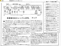
OTL SE(Not OCL) topolology schematic:One pure Tube,and two mixed, Tube,transistor and IC.Some old Japanese design,think work Ok but wery uneficient(power consumption/output power ,relation).I newer try this schematics.Salute . BTW- I see on your homepage many AM/FM RF transmitter apllication ,so question for You,did You ewer transmit(Radio Pirates) on the MW- AM band(1600-1800 khz)?
Attachments
OTL SE(Not OCL) topolology schematic:One pure Tube,and two mixed, Tube,transistor and IC.Some old Japanese design,think work Ok but wery uneficient(power consumption/output power ,relation).I newer try this schematics.
If I can point something out: Once you go OTL, you eliminate any advantage that single-ended otherwise offers. IOW, SE amps work with an OPT, and without that they have no clear advantage **if the OTL is properly designed**.
That is to say, that if the OTL works right, the distortion will drop to zero as the output level goes to zero. Many P-P amps have increased distortion at low power levels but OTLs don't have to be part of that.
100% Corect&Truth. Low level out signal ,vanish` in OPT or being distort beacose OPT Iron take him away during the magnetic pole change,OPT Iron take some energy from OPT coil for that(OPT Iron histeresis),results are bad low level definition.This is one disvantage of OPT based amps in line of several others
I read that ARG sound labs did build a direct coupled se amp. I believe it used 2 6c33c tubes in parallel biased at either 350 or 400ma per tube and an inductor as the choke load. They clamed 20w output I assume they were talking peak. I have asked
on several forums and no one seems to have this circuite and the company seems to
have vanished. By the way I believe transidental audio has a 1.5W single ended amp
that uses 4 6c19pi tubes in parallel per channel.
on several forums and no one seems to have this circuite and the company seems to
have vanished. By the way I believe transidental audio has a 1.5W single ended amp
that uses 4 6c19pi tubes in parallel per channel.
OTL SE(Not OCL) topolology schematic:One pure Tube,and two mixed, Tube,transistor and IC.Some old Japanese design,think work Ok but wery uneficient(power consumption/output power ,relation).I newer try this schematics.Salute . BTW- I see on your homepage many AM/FM RF transmitter apllication ,so question for You,did You ewer transmit(Radio Pirates) on the MW- AM band(1600-1800 khz)?
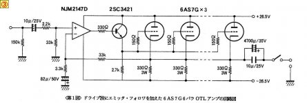
Actually OTL SE(hybrid) schematic nr 2 & 3 of Mr Ikeda is wery elegant.All stages are bipolar suplyed from same PSU(only +- 26,5V) and DC coupled,and output stage Idlle & stability is ensured thru the NFB feedback net(r5,r3,c2)to the pin 2(inverted input) of 1/2- NJM2147D OP Amp.But stel remain isue of Low eficiency(Power in/Power out) and Sound definition.
Yes these are actually very interesting ones, they are also using low voltages!!!
They also have a capacitor coupling, I have read that a good quality capacitor has better characteristics than a good quality transformer?
The most interesting point of an OTL is cost and lack of hard to find good output transformers. Safety is another issue.
To my personal taste 8W of power are more than enough, my system sounds too loud at even 4W, so efficiency is a second issue.
Has anyone build any of these low voltage versions? they should be quite safe even when everything fails. any reviews would be appreciated.
Last edited:
I can't help but wonder if those choke loaded SE OTL's will suffer from some of the same shortcomings as transformer coupled.
Yes choke made own sound `signature`very similar to OPT.This is due to Iron of choke and choke winding kapacitance,but the Amp is stel OTL(with all andvantages of OTL) but not OCL.Actualy output stage see two load in parallel-one is the Choke and other is the LOAD(SPEAKER).Salute
Yes these are actually very interesting ones, they are also using low voltages!!!
They also have a capacitor coupling, I have read that a good quality capacitor has better characteristics than a good quality transformer?
The most interesting point of an OTL is cost and lack of hard to find good output transformers. Safety is another issue.
To my personal taste 8W of power are more than enough, my system sounds too loud at even 4W, so efficiency is a second issue.
Has anyone build any of these low voltage versions? they should be quite safe even when everything fails. any reviews would be appreciated.
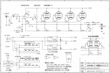
If you targeting SE OTL with out of ~10w think Mr Ikeda is OK one.Be sure that Capacitor coupled Otl is FAR better than any OPT based Amp,in this case good Rubycon photoflash elko(4700uf/35-63v=) well doo the job,and most important-whatewer hapened in output stage(mallfunction,arcinng...) there is NO chance to got long term DC in Speaker coil.There is no detail of bipolar PSU but I think trafo with 2x19v/1,5-2A (in original schematic is 4,3A signed)secondary well doo the joob too for- 4x6as7, 25 A greatz rectifier with CRC filter for both leg of bipolar PSU( in-4700uf/35v= via wire res 2R2/5w- and-4700uf/35v= out).there is in original PSU schematic two SS clamp diodes signed only with `D`.Beware beacose these clamp diodes have wery important role in AC power transfer of the whole Amp and final reproduced sound.Ultra Fast UF5408 diode is OK for that purpose(AC power clamping).BTW You not answered to me for `Pirate` Radio`
Last edited:
OTL SE(Not OCL) topolology schematic:One pure Tube,and two mixed, Tube,transistor and IC.Some old Japanese design,think work Ok but wery uneficient(power consumption/output power ,relation).I newer try this schematics.Salute . BTW- I see on your homepage many AM/FM RF transmitter apllication ,so question for You,did You ewer transmit(Radio Pirates) on the MW- AM band(1600-1800 khz)?
I find the second circuit very interesting. I guess each tube shown in the schematic is one of the two pairs inside the 6as7, so I need two 150ohm resistors for each tube and a total of 3 tubes (6 tube sections) per channel, am I getting that right?
Two modifications to propose:
1. One could throw away the semiconductor section and build a tube driver connected through the 150ohm resistors to the grids of the final tubes.
2. One could make a tube driver using ECC86 tubes for a full 26V operated amplifier
")
And two questions:
1. Will this 82uF and 3.3k still be needed for the cathode bias if using a custom tube driver instead of the solid state one?
2. Can I use more tubes on this schematic, say 5 in parallel for greater output and lower impedance?
- Status
- This old topic is closed. If you want to reopen this topic, contact a moderator using the "Report Post" button.
- Home
- Amplifiers
- Tubes / Valves
- 6C33C OTL DC schematic needed