Good evening all,
I just finished rebuilding my first 6V6 pp amp and I am having some hum issues.
The first build I had a hum/buzz that would be present when the amp started up but when a source was plugged in it would go away. Also when a source was plugged in there was a very slight hum when you put your ear to the speaker. I blame the lower hum on using a non-conductive material for a chassis and will address that after the main problem is found.
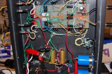
The second build I made a turret board with 1/2 spacers to keep it away from the heater wiring. I am still getting the same hum/buzz when a source is not connected, but it goes away when I connect an iPod. Also if I short the input terminal, the buzz goes away.
The input jacks are isolated, the earth ground is tied to the 3 transformer chassis for safety (not connected to the PS Ground).
Does this sound like a ground loop problem? Or a PSU problem? Both channels do the same thing. I am using a GZ34 rectifier tube.
Thanks
Brian
I just finished rebuilding my first 6V6 pp amp and I am having some hum issues.
The first build I had a hum/buzz that would be present when the amp started up but when a source was plugged in it would go away. Also when a source was plugged in there was a very slight hum when you put your ear to the speaker. I blame the lower hum on using a non-conductive material for a chassis and will address that after the main problem is found.
The second build I made a turret board with 1/2 spacers to keep it away from the heater wiring. I am still getting the same hum/buzz when a source is not connected, but it goes away when I connect an iPod. Also if I short the input terminal, the buzz goes away.
The input jacks are isolated, the earth ground is tied to the 3 transformer chassis for safety (not connected to the PS Ground).
Does this sound like a ground loop problem? Or a PSU problem? Both channels do the same thing. I am using a GZ34 rectifier tube.
Thanks
Brian
Attachments
That's a very nice build!
Schematic would be helpful, but I'll give it a shot...
Buzz.
Since the buzz goes away when the input is shorted or driven by a source, it is not a gnd loop problem.
So since the buzz happens when the input is floating, it is picking up stray HF. This can be adressed with (either/and/or) shielded wire to the input pin, grid stoppers at input (oh dread...), or something else...hehe, much help eh?
Low hum.
This is likely heater hum, but your wire dress is good to go, so my guess is the heater is grounded? If you bias the heater to a voltage >10volts higher than the cathodes, the hum should go away.
If the hum is not heater related, it may be layout, such as power tranny and OPT orientations, and many other things regarding layout.
My pennies...
Good luck")
Schematic would be helpful, but I'll give it a shot...
Buzz.
Since the buzz goes away when the input is shorted or driven by a source, it is not a gnd loop problem.
So since the buzz happens when the input is floating, it is picking up stray HF. This can be adressed with (either/and/or) shielded wire to the input pin, grid stoppers at input (oh dread...), or something else...hehe, much help eh?
Low hum.
This is likely heater hum, but your wire dress is good to go, so my guess is the heater is grounded? If you bias the heater to a voltage >10volts higher than the cathodes, the hum should go away.
If the hum is not heater related, it may be layout, such as power tranny and OPT orientations, and many other things regarding layout.
My pennies...
Good luck
Good morning - Yeah, I guess a schematic would help...
The mass diode bride bridge is to power the LED. I got lazy and didn't want to make a trip to Radio Shack so I used these 6A diodes that I had.
The input jack wire is a 2 conductor. 1 inner wire with a copper 'ground/shield'. They are both connected at each end.
I looked at a couple of things. There is a voltage difference of .2-.4 +/- volts between the input leads (+ and -) without a source connected. When a source is connected, the voltage is the same. That is why I thought maybe a ground loop.
Also since shorting out the + and - makes the hum go away, I used a resistor (250R) to touch across the leads, and the hum went away as well. I have the 470K installed per the schematic, but adding the 250R across the leads stops the hum. Could the 470K resistors be an issue?
Thanks for the help
Brian
The mass diode bride bridge is to power the LED. I got lazy and didn't want to make a trip to Radio Shack so I used these 6A diodes that I had.
The input jack wire is a 2 conductor. 1 inner wire with a copper 'ground/shield'. They are both connected at each end.
I looked at a couple of things. There is a voltage difference of .2-.4 +/- volts between the input leads (+ and -) without a source connected. When a source is connected, the voltage is the same.
That is why I thought maybe a ground loop.Also since shorting out the + and - makes the hum go away, I used a resistor (250R) to touch across the leads, and the hum went away as well. I have the 470K installed per the schematic, but adding the 250R across the leads stops the hum. Could the 470K resistors be an issue?
Thanks for the help
Brian
Attachments
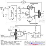
Well, I see no cathode resistor to gnd in the PI. Is this a typo? (should be in parallel with the 16V/100uF cap).
The input resistor 470kohms is high and therefore you risk picking up stray noise when input is floating. All modern sources will easily drive 10kohms, but to go somewhere in between I'd use 100kohms for that resistor.
(Actually, if it works fine when connected to a source I wouldn't worry about the buzz, but it aint mine so...)
About that slight hum.
The schematic doesn't show if the heater wires are gnd'ed or floating...???
Gnd'ing heater power, or better the center tap of the heater power, is a left-over from filament tube days. Per RCA manual, and many other litteratures, a indirectly heated cathode will not pick up hum if the heater potentail is above the cathode potential. 6.3VAC has a peak voltage of about 9volts, so biasing the heaters to at least 10volts above the cathode potential, will hinder any hum from entering the circuit. This done properly will be just as silent as DC heating, believe it or not (most don't believe it, I have tested and can confirm).
Anywhere between 20-80volts is fine for heater bias.
Well, I see no cathode resistor to gnd in the PI. Is this a typo? (should be in parallel with the 16V/100uF cap).
The input resistor 470kohms is high and therefore you risk picking up stray noise when input is floating. All modern sources will easily drive 10kohms, but to go somewhere in between I'd use 100kohms for that resistor.
(Actually, if it works fine when connected to a source I wouldn't worry about the buzz, but it aint mine so...)
From what I can see, there is no cathode resistor on the tag board for the input/phase splitter, and there is none on the schematic. With my limited tube knowledge, just having a capacitor here (the 16V/100uF) you will have an AC ground, but no DC ground, so I don't know how (or if) it works as shown.
The 10kohm feedback resistor gives a slight DC path...but how does this sound? The PI is way underbiased, it really shouldn't sound great, but who knows?
I'd stuff a 1kohm in place of the 16V cap you have now. It will bias the PI more correctly, and w/o the cap you get better phase splitting.
I'd stuff a 1kohm in place of the 16V cap you have now. It will bias the PI more correctly, and w/o the cap you get better phase splitting.
Hi all,
The schematic was taken from diyaudioprojects.com. It looked to be a pretty straight forward build. I have not added or removed components from the drawing.
I actually made the tag board myself and assembled the components based on the schematic.
Lastly, you are correct. I do have a strong electronic design/troubleshooting background. I can look at the shecmatic and put it together as drawn but I cannot tell you the difference between a grid stopper or a phase inverter (I can assume a PI changes the phase 180' but i cannot tell where it start and stops).
Also the 100R that is between pin 3 & 6 on the 6SL7 is soldered directly to the terminals of the tube socket.
I hope this info helps. But just to clarify again, the amp was build per drawing and I chose to build a pre-designed amp due to my lack of design experience.
Since you guys have been doing this a while, I will modify the circuit as needed to bring the amp up to snuff. If I need to take any measurements, I can do that later when I get home.
From what I have heard so far, I am less than impressed with the amp but I know I have a lot to learn. I also know there is some tweaking to do.
I can't wait to get this thing up and running strong...
Thanks for all the help
Brian
Checked the original and yes, it is as posted. The original had a 1K feedback resistor. This must have also been the bias resistor, which would be a more sensible value. This schematic is a little strange and unfamiliar to my less than experienced eyes, so some of the knowledgeable forum members will have to offer advice as to its suitability or any modifications.
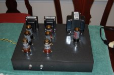
BTW, is this your first tube amp? A good effort! The layout is very neat and that will make it much easier for people to assist
My experience with hum is that it is almost always a ground return/loop issue. This is a great article that http: //www.aikenamps.com/StarGround.html I see you have star grounded at a point on your tag board. That point appears to be one of the mounting points of the tag board, so I assume that this is attached to the chassis as the chassis ground connect point?
I would modify your grounding scheme slightly. Keep the star on the tag board, but isolate it from the chassis. Have a separate sub-star for the power supply. Have this separate star point right at the second power supply negative terminal. Bring the first power supply capacitor -ive and the ground of the cathode resistor of the 6V6s to this point. Take a wire from this power supply ground and mount with a lug to the chassis. Make sure you use a star washer and scrape any paint/anodising etc from the chassis at this point. Then join the power supply ground to the star on the tag board with a bus or thick wire. The third power supply capacitor (22uf 350v) should be physically close to the 6SL7, as it is decoupling/filtering the power supply for the sensitive input stage. Ground it to the tag board star.
Oh, and grid stoppers are the 1K resistors on the 6V6s grids (and the 10K and 47K on the 6SL7 grids) and should be mounted right on the tube pins with no excess lead length. These help stop oscillation occurring from the inductance of the wires, hence right on the pins.
Someone else mentioned the grounding of the heaters. Have you attached the centre tap of the heater output from the transformer to ground? If not, you can make an artificial centre tap with two resistors. Improved noise performance is gained by elevating this ground reference voltage. The simplest method is to reference to the top of the cathode resistor of the output tubes. See here for reference and explanation The Valve Wizard
Good luck!
PS, any photos of the top side?
If you are looking for a good schematic with the same number/type of tubes, I think Gingertube may have built a Baby Huey with 6V6/6SL7 which is based on the Music Machine 6V6 Amp Audio Circuit; Parts Expo
try combining all the grounds and lift them one by one to see which one causes it.
i had once solved a buzz, by soldering a wire from the tube heater ground to the power supply ground. in another build, a fine wire from the input ground, to the chassis/power/heater ground solved the buzz.
i had once solved a buzz, by soldering a wire from the tube heater ground to the power supply ground. in another build, a fine wire from the input ground, to the chassis/power/heater ground solved the buzz.
Ok - Going by todays posts, I will remove the 16v cap and replace with a 1k resistor to see what that does. Also remove the 470K and replace with a 100K resistor? Anything else for now?
I also mis-typed in my last post. I do not have a strong electronic design/troubleshooting background. oops. lol
As far as terminating the c.t. of the heater output. Does this need to go to the earth ground or star ground? My chassis is made from a non-conductive material, so the earth ground is tied to the mounting bolts of the trannys (for safety). Should the star and earth be tied together?
Thanks for all the advice. Look forward to getting this amp running right!
Brian
Attachments
Here we go -
I think I found quite a bit of the problem.
First - As I said before, my chassis is non-conductive. The material works and machines lovely buy doesn't help with interference.
The turret board was built to keep everything neat, but the input stage area is where part of the problem is. if you look at the first pictures, you may see a red and yellow wire. These goto the Grids of the 6SL7. When I touch or move them the amp starts screaming like a Banshee.
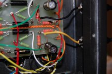
The input wire is 1 inner conductor with 1 'ground/shield' outer conductor. That goes to the turret board to the 10k input resistor, then from there a piece of silver plated/ teflon insulated wire to the grid (pin 1).
So basically I have made an atenna sensitive enough to pick up transmissions from outer space.
I am going to order some better shielded input wire and re-work the inputs to go straight to the tube socket and bypass the turret board. This will cut down on the length of wire plus give better sheilding. I will also rework the Grid wire (pin 4) that goes to 270k resistors.
That should take care of a good part of the hum. I will address the heaters as well. After that I will come back with an update and then we can see if we can get the rest of it knocked out.
Once I get to a certian point, and we think we need to keep going, I may explore the idea of scrapping top of the chassis and replacing it with 3/8" aluminum to help with RFI.
I want to thank everyone for the help with different ideas. It is greatly appreciated.
I'm off to order wire. I'll be back when I get the input rewired....
Peace and Thanks Again
Brian
I think I found quite a bit of the problem.
First - As I said before, my chassis is non-conductive. The material works and machines lovely buy doesn't help with interference.
The turret board was built to keep everything neat, but the input stage area is where part of the problem is. if you look at the first pictures, you may see a red and yellow wire. These goto the Grids of the 6SL7. When I touch or move them the amp starts screaming like a Banshee.
The input wire is 1 inner conductor with 1 'ground/shield' outer conductor. That goes to the turret board to the 10k input resistor, then from there a piece of silver plated/ teflon insulated wire to the grid (pin 1).
So basically I have made an atenna sensitive enough to pick up transmissions from outer space.
I am going to order some better shielded input wire and re-work the inputs to go straight to the tube socket and bypass the turret board. This will cut down on the length of wire plus give better sheilding. I will also rework the Grid wire (pin 4) that goes to 270k resistors.
That should take care of a good part of the hum. I will address the heaters as well. After that I will come back with an update and then we can see if we can get the rest of it knocked out.
Once I get to a certian point, and we think we need to keep going, I may explore the idea of scrapping top of the chassis and replacing it with 3/8" aluminum to help with RFI.
I want to thank everyone for the help with different ideas. It is greatly appreciated.
I'm off to order wire. I'll be back when I get the input rewired....
Peace and Thanks Again
Brian
Take the centre tap of the heater supply to the new star ground at the negative terminal of the second power supply filter cap. You want this power supply star at the second filter cap neg terminal to keep the largereturn currents away from your sensitive input stage.
I am going to rework the input wire and I will address this at the same time.
Thanks!
I would not worry too much about the chassis. I had my active crossover in an MDF box for years with no hum. Good layout will cure most of your problems I feel. I don't want that to come across as bad, as you have done a really great job with your neatness and layout. Understanding what is happening with the ground return currents will assist with working out the best grounding scheme. See the links posted above.
For the input wiring, Best way I can describe it would be to imagine that the tags attaching the 10K input resistor were to disappear. While keeping all of the other wires and connections in place, pull the end of the resistor that has the red wire on it to the input pin on the tube, so that the red wire is no longer required. That is it. I would also wire the 47K resistor on the other input grid of the 6SL7 directly to the pin. Same for the 1K resistors on the grids of the output tubes. This will help to stop some of the screaming.
Make sure that you do not touch anything inside the amp with your bare hands when it is running, you may shock yourself. As for screaming when touching the inputs, regular amps will do this too to some extent.
Now, I will give you some great advice for free (free for you I hope, as it sure as hell cost me the hard way!!!). Get a 220K 2watt resistor (or similar high value) and wire it directly across the two terminals of the first power supply resistor. It will provide a high resistance path to ground to discharge the power supply capacitors when the amp is switched off. This will save you shocking yourself from a charged capacitor (that could happen with present design even when the amp is disconnected).
I am pretty sure you will fix this up and learn a whole lot in the process!
Cheers,
Chris
- Status
- This old topic is closed. If you want to reopen this topic, contact a moderator using the "Report Post" button.
- Home
- Amplifiers
- Tubes / Valves
- 6V6 Hum Issues