I'm finishing up my pre-amp project and while I wait for iron for the new mono supplies I designed I'm having issues with regulated supply I need to work for the next couple months.
Its been working fine for the last 1.5 years but suddenly when I now adjust for target voltage/bias amp it goes into oscillation. Since I never had it at this voltage/amperage before I'm wondering if the supply or PT are being over taxed.
My target is 200VDC with 12mA of bias. The PT is a 1A HV.
In that past I've had it up to 240VDC but only at 6mA bias voltage. I spent the whole weekend troubleshooting and found if I adjust past 195V which is roughly 11.4mA the PSU begins to go into oscillation.
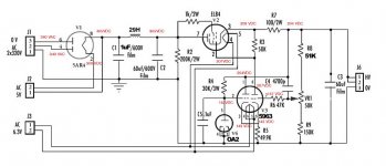
All the resistors, capacitor, tubes check out fine. I included the schematic. Maybe a PSU master can tell me what's occurring?
Its been working fine for the last 1.5 years but suddenly when I now adjust for target voltage/bias amp it goes into oscillation. Since I never had it at this voltage/amperage before I'm wondering if the supply or PT are being over taxed.
My target is 200VDC with 12mA of bias. The PT is a 1A HV.
In that past I've had it up to 240VDC but only at 6mA bias voltage. I spent the whole weekend troubleshooting and found if I adjust past 195V which is roughly 11.4mA the PSU begins to go into oscillation.
All the resistors, capacitor, tubes check out fine. I included the schematic. Maybe a PSU master can tell me what's occurring?
Attachments
Circuit comments:
What's C1 for? Why are C2 and C3 films? There isn't an electrolytic in the world that has too much ESR for this work (and honestly, you're fooling yourself if you think anything else could make a difference!).
V3 is biased quite low, or actually, very unbalanced. There's hardly any current through R3 as shown, yet (I'm guessing) ~5 times more when the output is unloaded. For better performance, it should be sourced from C2. Or you can eliminate the balance issue by using a pentode (put V4 in the cathode circuit), which will improve gain nicely as well.
Several voltages listed are impossible. Check your meter, I guess. For instance, how can there be apparently 40VDC across the 5AR4 heater? The inductor also seems to be dropping 100V. R7 seems to have 5V across it, suggesting a load of 50mA (you did not state under what conditions these measurements were taken). Maybe the 29H actually drops 100V under load (2kohm?), I don't know. It will get quite hot if it's true.
As for stability,
Your number one problem is C3 putting a big steaming pole in your response. You probably need bypass caps anyway, so you pretty well have to deal with that one. Maybe it doesn't need to be as big, but that's just changing the frequency anyway, which is approximately 1 / (2*pi*Zo*C3) = 14Hz.
Now, this seems to be more than low enough to put a damper in anything that could happen, and you didn't say what frequency, amplitude or waveform the oscillation is, so I have to guess here.
I do find it odd that you have extra delays around the error amp. I guess R6 is a grid stopper, and C4 is a "speedup" cap, enhancing HF gain slightly, and adding some leading phase, which will help compensate for the R6-miller C-R3 system. It looks odd to me that C4 is at the output though. I'd put it on V2 cathode. As shown, you'll get phase shift from the R7-C3 system, which will be 90 degrees (and lowww gain) at higher frequencies.
That said, I don't think it's a control loop thing. Even if it were oscillating, and at high frequency, there's probably enough phase shift in the system to do so, but with C3 there, you won't even see it, it will be too heavily swamped.
Sooo, check V4 and see if it's buzzing. With only 2mA (if the voltages are correct), it's not even running in the recommended range. If you need idle current that low, use a 0G3 (85V, 2mA), or zener diode, or smaller bypass cap (or none at all), or more bias.
Tim
Circuit comments:
What's C1 for?
For higher rectified voltage. If to increase it a bit the regulator may be stable on higher output voltage/current, if oscillations are caused by clipping of the EL84 tube.
I don't have any test equipment beyond a DMM and my ears. I get a low frequency hum mixed with some high frequencies and ticking sounds.
Speaking of ticking, 30K may be too high value: I would consider 5 mA of current as a minimum for a VR tube.
Wealth of info! Thanks everyone.
First, this supply was purchased on eBay as a one modeled on the Jadis PSU.
I changed it to a choke loaded PSU. Yes, C1 changes voltage.
It originally came with a OC2 diode but once I went to choke loaded I could not get enough B+ so I went with the OA2.
I the voltage on the 5AR4 was just Pin 8 to ground not across the heater. That voltage is dropped by 10VDC by the choke. I made an error on that schematic. Thanks for catching it. S/B 390vdc Consider the rest of the voltage accurate +/- 5V.
I will retake the readings again later in the day. The readings in the regulated section are a little old but my new readings were within +/-5V.
The film caps (ASC X386S) sounded far superior to the initial electrolytic that were in there.
C3 originally had a .1uF bypass in the circuit but my friend told me it was not necessary with a film cap so I removed it. I thought about maybe that could be one of the causes?
Last edited:
C1 increases voltage. Its just a voltage set. I don't believe this is an issue as a friend runs his non regulated supplies this way.
What size do you recommend to try for R4? What target voltage am I looking for there? I just looked at the OA2 data sheet and it says min anode is 185VDC. Yikes!
Sooo if I just run a jumper wire it would see 196VDC. Or I could just use a small resistor to bring it to min but I usually run tubes over min naturally. Possibly a dumb question but if I increase plate voltage will the overall PSU output be increased? I need to keep it within the range I have set although I can always play with R8 again to change the voltage range.
I suspected it had something to do with the OA2 tube since I swapped it in there replacing the OC2 tube.
Last edited:
C1 increases voltage. Its just a voltage set. I don't believe this is an issue as a friend runs his non regulated supplies this way.
Non regulated power supplies can't oscillate by definition.
Regulating tube EL84 need plate to cathode voltage to work properly. If it is too low it does not work properly.
What size do you recommend to try for R4? What target voltage am I looking for there? I just looked at the OA2 data sheet and it says min anode is 185VDC. Yikes!
As I suggested before, for minimum 5 milliamperes of current through the VR tube.
Edit: I would increase R8 instead of swapping a VR tube.
Last edited:
")
According to the tube data sheet for a EL84 I'm already exceeding voltage by 91VDC. It says its maximum is 300VDC so I don't think increasing its voltage is a good idea unless I'm really missing something.
I completely agree on the VR tube. Did you look at the calculations I did?
Also it looks like the present voltage is way too high for the original 0C2 (max 105v) and too low for the replacement OA2 (min 185v).
I completely agree on the VR tube. Did you look at the calculations I did?
Also it looks like the present voltage is way too high for the original 0C2 (max 105v) and too low for the replacement OA2 (min 185v).
Last edited:
According to the tube data sheet for a EL84 I'm already exceeding voltage by 91VDC. It says its maximum is 300VDC so I don't think increasing its voltage is a good idea unless I'm really missing something.
I completely agree on the VR tube. Did you look at the calculations I did?
Once again; I never said about maximum voltage. I said about minimum voltage. You may find plate curves in the datasheet and check for yourself.
Good luck!

... not enough of voltage for EL84 tube.
Sorry I was just reacting to the above
- Status
- This old topic is closed. If you want to reopen this topic, contact a moderator using the "Report Post" button.
- Home
- Amplifiers
- Tubes / Valves
- Oscillating PSU above certain voltage