Hey guys,
I'm about to go off to Auburn this fall, and I want to take my ST-70 with me. However, when I built my driver board, I used two pots with two large knobs on them so I could have 4 bias pots total. I didn't think about just how much these look like tone/volume controls! I haven't had any accidents yet, but maybe I'm just lucky.
I would like to fix this problem, not by replacing the pots (that'd be too easy, you see...! ) but rather by making an autobias circuit. Either I could use the op-amp approach or the constant current fixed bias method (any others?). I would really love to find a way to use the op-amp approach...but I fear it may be more costly in the long run. I'm ready to order about $30 worth of parts to make the CC fixed bias circuit for each cathode, but I want to see what ya'll think first.
The fixed bias would take away almost 40 volts from the tube...but how much power would I really be losing? Would this add much distortion? I'd be using a TL783 and a 1000µF 100V audio cap for each cathode. I don't run my amps at full blast. I'm quite conservative, really. I also keep the bias at 40mA.
Has anyone implemented an op-amp autobias circuit for an EL34/6CA7/6L6C? More specifically, on the ST-70?
I'd love to see some schematics if anyone has any. Thanks in advance!
Kyle
I'm about to go off to Auburn this fall, and I want to take my ST-70 with me. However, when I built my driver board, I used two pots with two large knobs on them so I could have 4 bias pots total. I didn't think about just how much these look like tone/volume controls! I haven't had any accidents yet, but maybe I'm just lucky.
I would like to fix this problem, not by replacing the pots (that'd be too easy, you see...!
The fixed bias would take away almost 40 volts from the tube...but how much power would I really be losing? Would this add much distortion? I'd be using a TL783 and a 1000µF 100V audio cap for each cathode. I don't run my amps at full blast. I'm quite conservative, really. I also keep the bias at 40mA.
Has anyone implemented an op-amp autobias circuit for an EL34/6CA7/6L6C? More specifically, on the ST-70?
I'd love to see some schematics if anyone has any. Thanks in advance!
Kyle
Autobias on an AB amp is tricky (remember, the tubes do NOT run constant current!). I'm still not sure why you'd put knobs on bias pots- once they're set, they hardly need readjustment. If it were me (and once upon a time, it WAS me), I'd just put trimpots in there, preferably in a spot where you have to know where to stick the screwdriver.
Alright, before I even THINK about taking this amp to college (well, I guess that might be too late...!), I will check out my dorm situation. I'm in the honor's college, so I hope things are a little less rambunctious over there.
This isn't JUST about making my amp college-proof. It's obviously a learning experience, a new experiment, and a great way to never have to get out my voltmeter again to check the bias (until something goes wrong).
I would still love to implement an autobias circuit in the amp. If I wanted to go with the constant-current fixed bias method (with a bypass cap), what would that do in class AB operation? Is there a better way?
Kyle
The first and VITAL step, before you fuss with minor problems, is to beer proof it with a water tight cover.
2nd, if you don't want to take the great advice of lockable screwdriver bias pots, just use plastic shaft pots and attach the B+ to your metal knobs. This will keep fingers clear, at least after the initial attempt to fiddle...
Then #1 really has to be in place!
Regards, Allen
2nd, if you don't want to take the great advice of lockable screwdriver bias pots, just use plastic shaft pots and attach the B+ to your metal knobs. This will keep fingers clear, at least after the initial attempt to fiddle...
Then #1 really has to be in place!
Regards, Allen
If I wanted to go with the constant-current fixed bias method (with a bypass cap), what would that do in class AB operation? Is there a better way?
Distort horribly after a few watts.
There's an autobias circuit based on opamps in Morgan Jones's "Valve Amplifiers" that would probably work. But really, you've got about a hundred years of tube amp experience in this thread all saying the same thing- use screwdriver-adjust (and even locked!) trimpots.
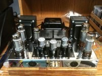
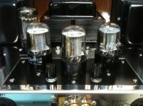
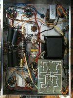
I have some pictures of my ST-70, which might help explain the challenge of installing another pot. My ST-70 has a driver board that I made (the circuit is a 6SN7 x3 Blackburn Audio driver) with two extra pots on it. I refuse to drill in my new chassis. Period. Any modifications will be done with existing holes on the chassis or modifying my driver board. Heck, I might even make a whole new driver board and install good pots on it this time.


They preferably need to be 1/8W pots (like I have in there right now). Can I get 1/8W pots that have a screwdriver adjust that mount by means of a nut? The lockdown part is optional, I suppose. I figure most people won't be touching something with a screwdriver adjust anyways, especially if it's right next to a hot 6SN7! In truth, the more flush it is with the chassis, the better. Any suggestions?
Thanks!
Kyle
kyle,
Possibly try cutting shafts almost flush and slotting with dremel tool etc, and making a bracket to mount pots below holes so you can stick a screw driver in hole. Have them mounted so cut off shaft ends are almost flush with metal plate. Just enough below so you can't use a finger nail etc. This way hole edge will make it easy for your screwdriver. Attach pots bracket to base plate and have screws on bottom to easily detach from base plate.
Randy
SY how many LEDs to make it glow in the dark (like really glow)?
Way too many!
Main problem is bias adjustment unless you convert the amp to pentode and set up an adjustable screen supply.
They preferably need to be 1/8W pots (like I have in there right now). Can I get 1/8W pots that have a screwdriver adjust that mount by means of a nut? The lockdown part is optional, I suppose. I figure most people won't be touching something with a screwdriver adjust anyways, especially if it's right next to a hot 6SN7! In truth, the more flush it is with the chassis, the better. Any suggestions?
Thanks!
Kyle
I would check either the Mouser catalog or Digi-Key; you should be able to find screwdriver-style controls, even locking ones, probably 1/4 watt. If you want this to really work right, I would avoid any additional complexity; barring that get a bigger chassis so you have room to lay things out right.
- Status
- This old topic is closed. If you want to reopen this topic, contact a moderator using the "Report Post" button.
- Home
- Amplifiers
- Tubes / Valves
- College-proofing an ST-70 (aka autobias+ST-70)