Member
Joined 2009
Paid Member
I've been building SS amps for about a year [http://www.diyaudio.com/forums/solid-state/167369-designing-tgm3-output-triples.html]], but a friend of mine who is an ardent tube fan couldn't suffer my blundering about with transistors any longer. This past couple of weeks I've been receiving bits and pieces as a gift. A chasis, some glass bulb shaped objects, a couple of strange looking objects which I'm told are paper-in-oil capacitors made in Russia before I was born and some Hammond iron.
So now I will try to learn about tubes (or valves as they call them where I come from)
I'm seeking a bit of encouragement and advice from the Forum as I go.
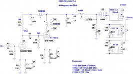
The schematic for which these parts are for is based on an old design known as Lilliput so it may be familiar to some of you.
So now I will try to learn about tubes (or valves as they call them where I come from)
I'm seeking a bit of encouragement and advice from the Forum as I go.
The schematic for which these parts are for is based on an old design known as Lilliput so it may be familiar to some of you.
Attachments
Hi, welcome to tubes, I have some thoughts...
- 6as7 often has poorly matched sections, so it is not the best choice for an amp without feedback... Also there are tubes with nicer curves around (the 6as7 was never designed for audio use.) It does have great looks, though.
- This amp will not have very much gain. Depending on your source, you may need to use 6sl7 instead of 6sn7 to get sufficient drive to the output tube.
- You have almost no current margin on your 155C choke. I don't know how close it is specced so you'll probably get away with it, but it would be bad news if it went into saturation during signal peaks.
- Remove LED1 and LED2, they don't serve much purpose and they'll cause nasty switching noise.
Kenneth
6as7 often has poorly matched sections, so it is not the best choice for an amp without feedback... Also there are tubes with nicer curves around (the 6as7 was never designed for audio use.) It does have great looks, though.
True, still the original Lilliput was built many times and is still being sold as a kit in Italy (audiokit.it)... maybe for its looks ...

The original Lilliput also uses the 6922/ECC88 as input tube that has more gain.
While those ESE125 are quite inexpensive they don't offer much in the bass department which the 6AS7G are capable of, so I'd think about better OPT's (1.4K:6 ohm was the original from Megahertz).
Good luck!
Hi, welcome to tubes, I have some thoughts...
- 6as7 often has poorly matched sections, so it is not the best choice for an amp without feedback... Also there are tubes with nicer curves around (the 6as7 was never designed for audio use.) It does have great looks, though.
Kenneth
The looks is the only thing I like about the 6as7. Don't waste your time with that tube, el84 and 6v6 are much much better. I did build the Lilliput and I was never happy with it. Tube is cheap but the power supply and the OT makes it expensive. It needs big caps and a big OT. Hard to drive also, hum likely a problem... I hate that tube
.It might be OK in PP but not for a SE amp.
Member
Joined 2009
Paid Member
Thanks guys, it's good to have company.
Well, the bits I have are provided as gifts from a friends junk box so it provides the easiest path for a first build - i.e. it's free. The looks might be important for the WAF yet...
How do you think I could build it / design it so that it would be relatively easy to upgrade the performance ? Would I be able to drop in a different tube and tweak the bias ?
The 155C, if I understand the concern correctly, it is that it's rated for 8mA and I'm already expecting a bias current of 6mA through it leaving only 1-2mA headroom for signal swings ? Doesn't C2 keep the signal out of the choke ?
Member
Joined 2009
Paid Member
Hi Wavebourn, thanks for welcoming on board !
Well, 6V6 and EL84 are Pentodes, which is different right ? It's like taking a BJT amp and changing to MOSFETs (for a SS guy).
Is it not possible to build this amplifier with Triodes ?
To triode wire a pentode is easy, it only takes one 330 Ohms resistor from the plate to the screen. Planet 10 is right, less problematic and better sounding.
Is it not possible to build this amplifier with Triodes ?
Nothing is more valuable than an experience!
You may use tubes you friend gave you then go forward and do something different to compare!
You may use tubes you friend gave you then go forward and do something different to compare!
And this goes on and on and never stops... which is what this hobby is about!
Member
Joined 2009
Paid Member
Thanks guys, I will take your advice. Perhaps I should incorporate some additional sockets to allow some 'tube rolling'. I've just come into two 6S19's for example.
I've come to the realization that audio amplifiers is a hobby that doesn't let you go....
Dave - that's a very kind offer, I will certainly plan to include the option in the design.
I've come to the realization that audio amplifiers is a hobby that doesn't let you go....
Dave - that's a very kind offer, I will certainly plan to include the option in the design.
Last edited:
Sorry to disagree with you guys, but 6as7g can make for a good push pull amp. The one I built measures less than 1% THD at full power using zero negative feedback.
I wouldn't recommend them for single ended use though. They do put out gobs of 2nd harmonic. But that cancels out in push pull.
I wouldn't recommend them for single ended use though. They do put out gobs of 2nd harmonic. But that cancels out in push pull.
Last edited:
Member
Joined 2009
Paid Member
Well maybe you can help me start off in the power supply ?
1) Rectifier:
I'm supposed to be getting a Hammond 270DX which gives me 550Vac C.T. at 104mA. So accounting for the C.T. my 5AR4 rectifier will see 225Vac per plate.
I allow for 60mA per each channel, or 120mA total.
I go and look up the datasheet (see attached) for a full bridge choke loaded supply and it tells me that I'll get maybe 200V for my B+.
Have I got this right ? (it's lower than the 250V I had marked on my schematic)
2) Power rail chokes
Now, it turns out I can't get the 158M supply rail choke but I do have a pair of 1157J chokes. These are limited to 65mA per channel so not a lot of room there. What does this current rating mean ? Is it a thermal limit or a core saturation limit ?
I assume that if it's a thermal limit I'm probably OK because in Class A the load on the power supply is reasonably stable ???
I assume that if it's a saturation limit I need to go get beefier chokes.
Attachments

Last edited:
Hi Bigun,
you might have a look at "PSU designer II" which is a free download from duncanamps.com, it allows you to simulate all the typical PSU topologies.
Regarding the choke both limits are of course there but while the thermal limit sets in very gradually, saturation occurs much more suddenly. The exact DC current at which a particular choke will saturate is also subject to tolerances so it is hard to tell upfront if it will work in your case. A choke input filter, by the way, is much harder on the choke than a capacitor input filter is. (Greater AC swings)
It would be interesting to simulate the supply in PSU designer and look at the choke current waveform.
Kenneth
Member
Joined 2009
Paid Member
First off, I failed my basic math. I took 550V and divided in 2 to get 225V - doh! I actually have 275Vac per plate at the rectifier. From the published curves, at around 150mA total I'd see 225V d.c. per rail.
I don't fancy using a simulator yet. My SS designs were all heavily simulated in Spice and it's rather a nice opportunity with this simple tube amp to eshew that approach for some good old honest data sheet curves and pen & paper calculations.
So perhaps the psu is settled at this point ?
Well, I have also been given a 5Y4G rectifier tube as an alternative to try. It looks really nice with it's bottle shape.
Member
Joined 2009
Paid Member
What about the Input Stage ?
There were some concerns about the gain of the 6SN7 and now with B+ closer to 225V (possibly lower if I use the 5Y4G) we don't want to drop more than 50V from this in setting the plate voltage. With a plate current of at least 6mA this would imply a plate load resistor of 5.6k in series with the 155C (2.75k). This seems awfully low to achieve decent gain and linearity. Something needs to change.
If I remove the plate load resistor (and associated capacitors) and rely on the 155C as a choke load I get better gain, linearity and plenty of plate voltage.
Isn't that looking better ?
5k6 is way too low for the 6sn7. Since you're a little short on voltage, it's definitely worth a shot to go with the choke load. Not a bad idea at all. 60H and 2k7 DCR will get you about 10k at 20Hz which is reasonable.
Don't forget to adjust the cathode resistor too, I think 1k or 1k2 would be about right.
Kenneth
Don't forget to adjust the cathode resistor too, I think 1k or 1k2 would be about right.
Kenneth
I actually have 275Vac per plate at the rectifier.
275 x 1.4 = 385 V RAW DC less voltage drop across the rectifier, and the Rs & Ls in the series legs of the PSU filter.
dave
- Status
- This old topic is closed. If you want to reopen this topic, contact a moderator using the "Report Post" button.
- Home
- Amplifiers
- Tubes / Valves
- my CELLINI triode amp