Hey guys!
Pretty sure this is my first post.
Im building a tube preamp for bass guitar and Ive got it all wired up basically but Im having trouble with the tube heaters/filaments. This is my first attempt at anything with tubes.
I just want to check that I am on the right track. The preamp has two 12ax7's wired in parallel off one dc out, and two 12au7's wired in series, each 12au7 being powered by one dc out, so there is 3 12.6v dc outs on the power supply/rectifier board. For the DC3 out for the 12ax7's, I have two wires coming off the positive, each wire going to pin 4 on the two 12ax7's, i then have a wire connecting pin 4 and 5 together on each 12ax7. I then have two wires running back to negative on the DC3 out. Each negative wire coming from pin 9 of each 12ax7. Is that the right way to do it for parallel 6.3v wiring? The tubes light up nicely exept that I still read 12ish volts, even though the two 12ax7's are running off one 12.6v output. Also the heatsink is getting really really hot, like you can only touch it for a few seconds, is that normal?
Now the 12au7's. These are not meant to be in parallel and are meant to have 12.6v to each tube. So I have two DC 12.6v outputs for each 12au7. On each, I have a wire from positive of one DC output to pin 4, then a wire from pin5 to negative on the DC output. The problem is, they are not glowing barely at all, they get slightly warm aswell as its heatsink.
Now for the rectifier tube (6x4). 6.3v does go into the filament, and I measured pin 7 at 337v (red from multimeter to pin7 and black from multimeter to ground on power supply board, think that may be wrong) but the tube isnt glowing and Im not reading any high voltage at the B+ out. No idea whats going on.
Help will be greatly appreciated!
Myself and maybe others here got lost halfway thru your descriptions...perhaps you could post a schematic of your 'pre' so we could take a gander at it. I would guess if you follow thru the schematic as we do you might very well get that "A Hah" reaction.....Yourself realizing your mis-wire.
The 12XXX series tubes with the 12.6 & 6.3 wiring "options" can really get you turned around sometimes. Walking away for awhile & returning later with fresh eyes usually will reveal your mistake....rather obvious one at that.
_______________________________________________________Rick......
The 12XXX series tubes with the 12.6 & 6.3 wiring "options" can really get you turned around sometimes. Walking away for awhile & returning later with fresh eyes usually will reveal your mistake....rather obvious one at that.
_______________________________________________________Rick......
I got lost ")
But for the 6X4 connections:
Transformer high voltage secondary wires should connect to pins 1 and 6, and the center tap of the transformer winding should connect to the common negative/ground of the power supply. If you missed the center tap connection, that will probably be why you don't see any B+ output.
Transformer 6.3v secondary (if that is what you are using for the heater) should go to pins 3 and 4
Output DC to filter choke/capacitors is on pin 7 (as you measured 337v which seems reasonable).
Without a schematic we are shooting in the dark as to the other problems, sorry.
Last edited:
I got lost
But for the 6X4 connections:
Transformer high voltage secondary wires should connect to pins 1 and 6, and the center tap of the transformer winding should connect to the common negative/ground of the power supply. If you missed the center tap connection, that will probably be why you don't see any B+ output.
I think I did miss the center tap going to ground. The high voltage is 280v, so Ive got the 280v pin and the 0v pin from the transformer connected to the power supply board, by center tap do you mean the 0v?
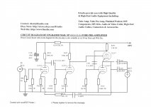
I found a diagram that explains the wiring of the tubes so i went with that, seems ok except that the tubes barely light up, they do get fairly hot though, the heat sinks dont burn your hand either. Attatched is that diagram.
So the only problem I have is figuring out why Im not getting any B+ and why the rectifying tube isnt heating or lighting up. Faulty tube?
So the only problem I have is figuring out why Im not getting any B+ and why the rectifying tube isnt heating or lighting up. Faulty tube?
Attachments
OK, if I understand, you are saying that the problem is no B+ out at the output of the power supply board? You are, however, getting 337 at pin 7 of the rectifier? It would appear that the rectifier is working then.
Rotorspec mentioned the centre tap of the transformer to get a voltage. I think the two silicone diodes on the anodes of the rectifier valve form a hybrid bridge giving the ground. If you measured between pin 7 of the rectifier valve and ground and got 337 volts I am assuming that this part of the circuit is OK, ie silicone diodes ok. The problem would therefore be 'downstream' of the part of the circuit that is demonstrated as working. I would suspect a problem with the voltage regulator section of the power supply. This is the section including the MR856, C9013 and the two zenner diodes and D3. I would confirm by attaching the ground (black) lead of your multimeter to the ground of the power supply and work 'downstream' with the positive lead. To do this safely, I would make sure that the multimeter lead is equipped with a clip of some type, so you can safely have your hands out of the way when you are applying power, as the voltages are quite dangerous. So, I would probe pin 7 of the rectifier and re-confirm you got voltage there, then probe the + side of C1, then the + side of C3, the junction of D4 and R2 (this is the top of the zenner string that sets the 280 volts, you should see 280 volts here), then the + side of C7.
I am a newb too, and will not be able to help with the failure of the regulator too much, but someone here will be able to help once we zero in on the problem!
Did you solder the components in to the circuit board of the power supply, or was it supplied completed?
BTW, at first glance, your wiring of the heaters looked ok. Lets sort out B+ problem first.
Good luck!
I think the two silicone diodes on the anodes of the rectifier valve form a hybrid bridge giving the ground.
yep that is correct.
ok sweet Il have a crack at that!
I bought it complete so Ive only been soldering wires for tubes, transformer and so on.
Ok, I got out my mulitmeter again and got about 337 V ac on both diodes on the ends that connect to the H. AC input (the diodes labelled D1 and D2 on the power supply schematic attatched in a previous post). But on the other ends of the diodes that connect to the rest of the board basically, I get nothing at all. I also measured all the caps and other components after these two diodes and i get nothing ofcourse.
First of all, there is no center tap. The rectifier is a hybrid bridge, with the tube as two of the diodes and the semis the other half. The ground is at the lower right corner of the power supply diagram, or it could be at the top end of R5.
The rectifier tube will light if the 6.3 AC reaches its heater pins.
I think regulating the other heaters isn't such a good idea. Those regulator ICs will get hot; the dissipation will be equal to the difference between their 12V output and the input (which seems to be 25V) multiplied by the load current. Load current would be 150 mA per tube. So 13V across the regulator times 150 mA gives about 2 W if it lights one tube, and 4W if it lights two. The combination will dissipate 6W, not too much and certainly not enough to burn yourself on a decent heat dissipator.
To keep the regulators cool, I'd add a resistor in series with their inputs to drop it to maybe 17V instead of its present 25V. This would allow them to run cool as cukes.
If the rectifier tube doesn't light, the other two diodes still will rectify. But there won't be a return path so it should have no output.
My private opinion is that this is a kluge. But it should work.
OK, as mentioned above, your setup is what is called a hybrid bridge. Most of the time with a tube amp you will see a setup using a centre tapped transformer like this link The Valve Wizard Your setup uses a pair of solid state diodes in combination with a valve (tube) rectifier to give a bridge rectifier that does not require a centre tapped transformer, see 4th diagram down here The Valve Wizard
Just to make sure we are talking the same terms, I will use the term 'valve rectifier' and 'silicone diode'. The silicone diodes are D1 and D2 on your diagram. The valve rectifier is the 6x4.
When you measure your voltages as described, do you get any voltage at pin 7 of the rectifier valve? If no, then you will get no voltage downstream, and the problem is the rectifier valve, or something 'upstream'.
Since you say you are getting a voltage reading at the cathode (end with a stripe on it) of the silicone diode, I would say that you are getting high voltage from the transformer. This would make me suspect the rectifier valve. Could be a couple of problems there:
No heater voltage - measure the voltage across pins 3 and 4. That is - place the two multimeter probes on pins 3 and 4. You should see 6.3 volts or close to it.
Check the continuity of the circuit board to the pins of the rectifier (ie bad solder joints). I would unplug the power supply from the mains, then put your multimeter in resistance measuring mode and measure the resistance from pins 1 and 6 to the traces on the circuit board coming from these pins. You should see a very low number here (less than 1 ohm). Remember, the pins on valve bases are numbered clockwise from the gap as seen from below. Here is a link to the datasheet for this valve http://www.r-type.org/pdfs/6x4-1.pdf
If these check OK, as mentioned above, you probably have a bad rectifier valve.
Not sure of a site in Australia for a source for this cheap, but these guys had one listed for $9 http://evatco.com.au/webcat1p4.htm and I saw some on ebay, one in Hong Kong for about $10 shipped (search 6x4 rectifier, or EZ90, or you will get nothing but box trailers!)
Good luck!
Last edited:
While I wait for a new 6x4 tube to come in the mail, Im going to sort out the pots and jacks and start drilling all the required holes on the chassis.
I was thinking of having Gain 1, Gain 2, Bass, Treble and Master. For Gain 1 Id have a pot at the very start of the whole preamp, for Gain 2 id have a pot inbetween the tone/eq circuit and the second preamp, then for the Master, Id have a pot at the very end of everything.
In > Gain 1 pot > first preamp (left) > tone circuit (bass and treble) > Gain 2 pot > second preamp (right) > Master pot > out.
Will that all work? Can I go without the Gain 2 pot or would it be good to have it? I plan for the whole preamp to go into a solid state bass amp.
Last edited:
The other 6x4 tube I ordered came in the mail, I plugged it in, it heats up and I now get the B+ voltage. Ive got jacks wired onto it to see if I get sound and I do, its nice and clean, not too much noise which is good. The tone circuit works really nice, except that I need to replace the 1m pot for treble to a 4m pot. Ive got a question regarding the preamp tube heaters. The tube warm up, they dont get heaps hot though and they barely glow, they each are getting 11.8v dc. Is that ok? I was expecting them to heat up a fair bit more. Does the amount of heat/glow the tubes produce effect the overall output sound? How can I overdrive the tubes to get that nice sound?
11.8 V is down maybe 6% extremely close to a +/- 5 % variance.
Thats just fine. There is some debate about undervoltage for filaments to extend lifetimes. Seeing the glow can be deceiving as some filaments are more observable than others.
_______________________________________________________Rick....
Thats just fine. There is some debate about undervoltage for filaments to extend lifetimes. Seeing the glow can be deceiving as some filaments are more observable than others.
_______________________________________________________Rick....
- Status
- This old topic is closed. If you want to reopen this topic, contact a moderator using the "Report Post" button.
- Home
- Amplifiers
- Tubes / Valves
- Tube preamp build help-heaters