I've spent the weekend punching and drilling a chassis with the following holes;
two sets of RCA inputs
speaker outputs
IEC socket
feedback selector switch
input selector switch
on/off switch
4 power tube sockets (6V6)
2 pre-tube sockets
volume pot
transformer holes (mains, two output transformers)
I'm a solid state diyer & just wanting to start out with a 6V6 push pull ultralinear amplifier.
I've got two Hammond 1615 transformers, and this as a mains;
http://www.mableaudio.com/www-web/cpmore.asp?id=143&typename=power transformers
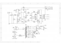
Does anyone have a simple circuit with a solid state power supply I can try?
I've done *a lot* of searching and they all seem to have valve rectified power supplies - I just can't fit that on my chassis, and would prefer to go with what I know.
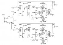
I'm thinking of the attached one, but there are absolutely no values given for the wattages of the resistors and voltages of the capacitors, plus it doesn't seem to have a volume pot in it.
Look forward to any suggestions.
Cheers!
two sets of RCA inputs
speaker outputs
IEC socket
feedback selector switch
input selector switch
on/off switch
4 power tube sockets (6V6)
2 pre-tube sockets
volume pot
transformer holes (mains, two output transformers)
I'm a solid state diyer & just wanting to start out with a 6V6 push pull ultralinear amplifier.
I've got two Hammond 1615 transformers, and this as a mains;
http://www.mableaudio.com/www-web/cpmore.asp?id=143&typename=power transformers
Does anyone have a simple circuit with a solid state power supply I can try?
I've done *a lot* of searching and they all seem to have valve rectified power supplies - I just can't fit that on my chassis, and would prefer to go with what I know.
I'm thinking of the attached one, but there are absolutely no values given for the wattages of the resistors and voltages of the capacitors, plus it doesn't seem to have a volume pot in it.
Look forward to any suggestions.
Cheers!
Attachments
Last edited:
sure does have a volume pot - right after the inputs, 500k dual gang.
resistors will be either 1/2 or 1W in most locations. Metal films are fine, but in a couple of locations carbon is much better suited.
Caps will be high voltage - estimate at 1.5 to 2 times your B+ working voltages. Typically 630V though.
Don't sweat the SS vs tube rectification thing. Download Duncan Amps PSUD II software and start playing.
THe schemo you have is...ok. There is a lot that could be done to extract a lot better performance at very little additional cost (and possibly less...)
Ask lots of questions. And go look at the thread on Chris's 6L6 project for some excellent design thinking.
Last edited:
ok, the sl7 is going to be the WRONG unit here...
Yes, it will fit (physically) and yes, you can make it work, but only so far outside its happy place that its not worth the effort.
The sl7 is just about a pure voltage amp - it's gutless in terms of drive capability into a load. regardless of what it looks like, the grid of a 6V6 is a load. You will have all sorts of issues in driving against the miller capacitance of the outputs, slew rate issues etc etc.
Again, refer to the AB2 thread and read it through thoroughly.
Also, figure what valves/tubes you can access at reasonable prices and with minimal hassle. One for each slot is not enough - you will need at least 1.5 times as many as you have places for so you can ensure a reasonable match between units ie, where you need 4 tubes of a type, you need 6 minimum available to you.
Since you have SS experience, consider driving the output tubes with sand. Its like swearing in the chapel to say so in here (well, for a few...) but the use of a solid state or chip front end gets around a lot of issues (drive current / slew rate etc) , and allows you to concentrate on learning about glass and iron outputs...
In pp AB1 you need to be able to swing +/-19V at the 6v6 grids to get around 14W out. Thats not tough at all using sand. Later, if you want, you can put a glass front end on very easily.
- Status
- This old topic is closed. If you want to reopen this topic, contact a moderator using the "Report Post" button.