Does anybody here know the typical gain values for a long tail driver/inverter
section as seen in the classic Fenders and Marshall amps?
I'm looking for a general range here and the answer can include 12AT7 - 12AX7
differences as well as small power vs big power.
In other words, how much gain(typically) is the driver circuit by itself supplying
to the output section. Electronic or in dbs is fine.
Thanks
Voltage gain of a singly-driven diff amp is expressed as:
1/2 ((mu*Rl) / (Rl + rp)) where;
Rl is the load resistance, typically the load resistor resistance in parallel with the following stage grid resistor,
rp is the plate resistance of the device at the quiescent operating point,
mu (μ) being the ratio of gm (grid transconductance) to plate conductance(the inverse of plate resistance).
Poinz
AudioTropic
Did some number crunching and everything looks good. Most answers were roughly .25 of mu
That formula was the missing link - I had been trying with the standard single stage formula but that didn't seem right.
28db is higher than I'd expected but it turns out to be just the right number for what I'm trying to do with an insert design.
Thanks again
That formula was the missing link - I had been trying with the standard single stage formula but that didn't seem right.
28db is higher than I'd expected but it turns out to be just the right number for what I'm trying to do with an insert design.
Thanks again
Av is actually the same as a common-cathode (plate loaded) amp with a fully bypassed (or no) cathode resistor, from plate to plate. Voltage gain of each device is one half that. Whether it's a quarter of μ depends on the load resistance in relation to the plate resistance. I get more like a third of μ usually, because I don't like to load the devices heavily.
Aloha,
Poinz
AudioTropic
Aloha,
Poinz
AudioTropic
Using the classic 12AT7 circuit from the early BF period (plate loads = 82K & 100K, 1M grid resistors, 470 ohm cathode resistor, 22K tail resistor), the gain from the 12AT7 input grid to either output tube is 19.25. This can vary 2-3% based on different tube examples, but otherwise you can take this to be an accurate value, based on measurements taken years ago in a test cell model, where precision parts were used, and the measurements taken.
Dave
Dave
Does anybody here know the typical gain values for a long tail driver/inverter section as seen in the classic Fenders and Marshall amps?
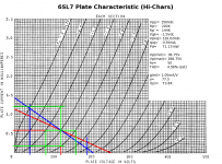
This is figured with loadlines, as seen here (attached). Draw the DC and AC loadlines as for a single stage to see what your gain, output swing, and estimated THD is going to be.
Once you have that, the gain per phase of your LTP will come in as half of that single-ended gain. With LTPs, half the input voltage appears as Vgk, and half appears across the tail load.
In this case, the loadline predicts Av= 50, single-ended. When this was actually constructed, the measured gain per phase turned out to be Av= 25 / phase -- a 0% error!
")
Attachments
- Status
- This old topic is closed. If you want to reopen this topic, contact a moderator using the "Report Post" button.
- Home
- Amplifiers
- Tubes / Valves
- Voltage Gain on Long Tailed Drivers