I'm putting together the final ideas for an amp. I have a question since I haven't built my own before. I know there are people more knowledgable about this than I am. I'm going to use PP and I'd really like to use a toroid OPT, but it requires no D.C. going through it.l I'm really interested in using garter crossfeed because its simple and appeals to my aesthetics. I think for a toroid manual balancing really isn't ideal.
The problem is I'm also interested in running ab2 to get enough power for 83db efficiency speakers. Are these two ideas incompatible? Can one use garters in that situation where there's little or no cathode feedback. I'm going to be driving the output tubes with source follower mosfets. Any help would be greately appreciated. Thanks in advance.
The problem is I'm also interested in running ab2 to get enough power for 83db efficiency speakers. Are these two ideas incompatible? Can one use garters in that situation where there's little or no cathode feedback. I'm going to be driving the output tubes with source follower mosfets. Any help would be greately appreciated. Thanks in advance.
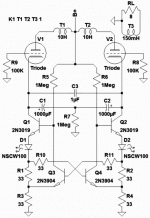
Yeah, you can certainly abuse Garter Bias to
precisely match CSS, keep the toroid happy...
Last I visited this I was mostly interested in
Class A. I hadn't really thought how to deal
with AB2 currents... But as long as the grid
and screen currents all draw in parallel with
the plate on the same side of the winding,
should be OK.
Return the drain of your source follower drive
to plate, your AB2 current is all accounted for.
Same thing with your screen Regs...
Garter should see same currents as the toroid.
Even if you just garter on the tube cathodes,
prolly don't need all the sand I've thrown at it.
This is a very slack drawing, not checked for
errors. Take with a grain of half baked salt.
You want bypass caps to GND instead of the
bridge between the cathodes for AB anything...
Wasn't properly thinking AB when I drew that.
Attachments
Last edited:
Thanks for the input. I looked at your schematic and it was really interesting. Instead of using two dividing resistors per side as in the original garter design you are using one ccs per side each modified by a transistor crossfed from a resistor network below each ccs. I think I get it. I also think I understand why you would have to use 2 big caps to bypass the whole shebang on each side to allow for variations in current. There was a related thread, that I started that I can't seem to come up with now, where separate floating power supplies and some gyrators were involved. I never really understood that idea and I never want to build something I don't understand. It also offended my KISS sensibilities. This idea makes a little more sense too, maybe my own limitation regarding excess complexity.
I think your idea of putting the mosfet drain and (possibly) screen supplies through the OPT input winding might have a lot potential. I never thought of that. I will have to think on this.
Thanks Poin for any help you can round up also. I think I'll need it.
Eric
I think your idea of putting the mosfet drain and (possibly) screen supplies through the OPT input winding might have a lot potential. I never thought of that. I will have to think on this.
Thanks Poin for any help you can round up also. I think I'll need it.
Eric
I have a little headphone amp which uses toroidals and Garter bias - just the simple type. As far as I understand this only works in strict class A. It works very well even with very small toroidals which indicates that it keeps thing matched to less than 1mA.
John Broskie recently revisited the idea and changed one of the stack of resistors for a transistor to avoid the voltage wastage.
Shoog
John Broskie recently revisited the idea and changed one of the stack of resistors for a transistor to avoid the voltage wastage.
Shoog
For a class AB with good performance and DC matching, the best route to go would be fixed bias with DC servo circuit.
But if you are set on cathode biased class AB; a current mirror biasing configuration would be your best bet. Standard garter bias will work in class AB for DC matching, but the amps performance will otherwise be worse than other forms of biasing. In class AB, current increases with signal amplitude. The more current which flows through the tube means the more voltage those biasing resistors are going to hog (it also changes Vgk, which makes the outcome less predictable). This is why cathode biasing in general is considered less desirable than fixed bias for class AB. Now, when you consider that garter bias requires even more resistance (usually x2) in the cathodes current return path, you can start to understand why it would not be good for use in class AB.
CCS cathode biasing approaches won't work at all for class AB. It will only allow the amp to run in it's class A region.
My original intent was to direct bias using mosfets but have not figured a way to match currents automatically in AB. I've been trying to avoid the route Norman Koren went with individual servo circuits for each tube. In spite of how he describes it as relatively simple it didn't seem simple to me. I'm trying to avoid that complexity at all costs just to maintain my audio sanity. (If you've noticed, I haven't heard of anyone trying to replicate his success. I think it might be kind of hard to.)
Yeah, I see what you're saying. I was thinking about this and as the gears were grinding, so to speak, I realized that just putting the power supplies for ancillary current hogs through the plate circuit will not work. Besides the situation you are talking about gradual increases in power required with increases in audio level there is also the extreme situation of drawing current through the grid in ab2. I was going to use the garter system only to match currents, not to bias the circuits. That was why my original question was if direct biasing was incompatible with a garter? It may be that it just is.
I'm still not completely convinced, (though I'm getting there) that it can't be done. I can envision using the garter system simply to match the two sides of the OPT exactly and having the usual powerdrive mosfet provide the bias. It would in effect be a combination bias system.
There needs to be another element in it too though. There has to be some kind of current sensing system that take a sample of the power supply draw to open up the transistors/mosfets in the cathode circuits for change current demand. SO in that way it would be a servo system. It was really mislabeling on my part to call the active devices in the cathode a CCS. It is more of moving target than that. I think this can be done without going to the complexity Norman Koren went to. That just seems wrong to me. I would think you could get away with one or at most two current sensing resistors that you tap off of from the power supply somewhere to create an added signal out to both active device in the cathode circuits. This is just for one channel. I really do like the garter system because it can be applied to any number of tubes in parallel by just moving the current sensing resistors to a point where the cathodes combine. I'm not that much worried about current hogging as you can still put in a small adjustment pot in each individual tube cathode circuit for that.
If you are thinking about a servo system that is simpler than Koren's then let me know.
Actually after having written this all down it clarified in my mind what I have to do. Rather than reinvent the wheel with a garter system for AB I should modify the servo system used in Koren's TENA amp for the reduced complexity I'm seeking. I was, and still am, turned off the requirement for individual MOSFET direct drivers for each in tube in a parallel setup. So I'm not going there, not because it might not be better but because it just more to go wrong and engineer and on and on. But I think I can stand the complexity of the same bias system feeding off a "combined" cathode sense resistor for all tubes on one side. Then I'll just use one master cathode resistor to create a system to drive the other sides MOSFET servo to match it. It actually will be very similar to NKs system. There will be three changes though:
1. It will use MOSFET drivers/biasers.
2. It will have one driver/biaser per side instead of for each tube.
3. It will have small cathode pots (10 ohms?) in each tube cathode circuit to approximately match individual tube currents.
I think this will work without driving me crazy.
1. It will use MOSFET drivers/biasers.
2. It will have one driver/biaser per side instead of for each tube.
3. It will have small cathode pots (10 ohms?) in each tube cathode circuit to approximately match individual tube currents.
I think this will work without driving me crazy.
I don't see how this adds resistance to the cathode nor can't be used for AB.
The traditional garter has bypass caps from each cathode to GND... Oh, DuH!
Now I get it... AB quiescent current is less, so you can't just fix up a pair of
of identical CCS. They need to center upon fixed voltage, which means they
need to be GyroCCS or something like that... But then how might they also
be made to mirror the same currents over the long haul?
There's always 3rd leg shunt regulator dumped into the cathode resistor(s)?
But you'd have to carefully split that current equally into both garters to
keep AB bias voltages from wandering, and the torroid currents to still get
gartered without confusion.... Lemme think on this, I'm not so sure anymore
what is or ain't possible or reasonable. My reasoning prowess seems to have
fallen apart right when I need it most, damn this getting old...
Last edited:
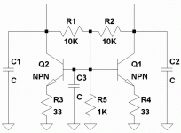
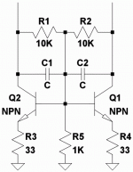
Its not Garter like you wanted. But maybe will do the trick?
Compromise between VBE multipler (fixed voltage) and current mirror???
The second gyro based is either genius or sheer idiocy?
I've been drinking, so there really no telling...
My vote is for idiocy.
I'm not up to running a full sim right now...
Compromise between VBE multipler (fixed voltage) and current mirror???
The second gyro based is either genius or sheer idiocy?
I've been drinking, so there really no telling...
My vote is for idiocy.
I'm not up to running a full sim right now...
Attachments
Last edited:
Here are the schemes I've been messing around with for class AB DC matching.
An externally hosted image should be here but it was not working when we last tested it.
Thanks very much to all for the help. Apparently this was a problem that was ripe to be worked on. I think the current mirror idea is much simpler than a servo system. Great minds seem to think alike so I think I will take that cue from the small majority here and try to go in that direction. I think I can deal with this level of complexity.
Am going off to visit me old mum so will be away for a few days. I can do a cogitate on this problem during the visit. Thanks again.
Am going off to visit me old mum so will be away for a few days. I can do a cogitate on this problem during the visit. Thanks again.
- Status
- This old topic is closed. If you want to reopen this topic, contact a moderator using the "Report Post" button.
- Home
- Amplifiers
- Tubes / Valves
- Garter cross-coupled feedback


