So I finally finished my guitar amp. There are numerous problems!
1) there is an insane amount of 60 Hz hum
2) the output is VERY VERY low, barely audible, less loud than the 60 Hz hum
3) the first preamp tube socket is extremely loose. it barely keeps the tube in when the amp is upside down. The socket is this one: Parts-Express.com:9-Pin Tube Socket Gold Plated Ceramic 12AX7 Type w/Bracket | tube socket chassis pc mount 8pin 9pin 4pin 7pin ceramic new sensor newtube07
I think the hum is because my star ground is kind of close to the heater supply. The output is also close to heater supply wires. Im not sure if I can even salvage this chassis / build.
I'll try to get pictures up!

3) the first preamp tube socket is extremely loose. it barely keeps the tube in when the amp is upside down.
Until you source a socket that works, all bets are off!!
Buy another socket..
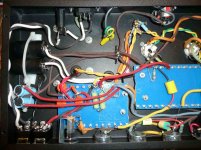
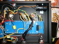
I just ordered a new socket, and the chassis is painted, but I sanded a spot and soldered the ground from the wall there, you can see the green wire in my pictures coming from the power socket. The star ground connected to the chassis via a screw. Its the thing with about 10 brown wires going into it.
I really think its because the sockets bad, and the heater wires are literally right next to my star ground... bad layout on my part.
I really think its because the sockets bad, and the heater wires are literally right next to my star ground... bad layout on my part.
Looks like you have the two sections of V1 tied together in parallel but incorrectly. Pin 1 should be tied to Pin 6, 2 to 7, 3 to 8; it looks like 1 to 8, 2 to 7 and 3 to 6, am I right? I don't think that will work very well. Since you are replacing V1 socket no biggie but the tube might have been ruined. Check all other sockets for correct wiring while you are at it, we've all been there done that.
Craig
Craig
Last edited:
Are your heater wires well away from the signal wires, ie, tucked into the corners and running along the edges of the chassis coming out to the sockets only where needed? If you have to cross heater and signal wires, try not to run them parallel near each other, ie cross them at (or close to) right angles.
That looks way neater than some of my dodgy guitar amp efforts! Congrats. It should be fairly hum free once you get it working.
You can tighten most sockets up by taking out the tube and carefully bending the pin holders with a small jewellers screwdriver. I find it strange that a brand new socket would need it through!
As always, double and triple check every single connection and solder joint- I always physically wriggle the leads of components to check for bad connections.
Also you might like to check that your component values are all correct.
Well the heater wires are pretty out of the way, I did not feel it was necessary to run them all the way to the back and then up again and then back again and then up again, especially for 3 tubes. If you think this will help a lot, perhaps I'll do it for the two preamp tubes, as the power tube is right in front of the output jack, and it would be hard to do there without going right up against the output jack.
I will put the new socket in, set up the first preamp tube CORRECTLY, and see what it sounds like. I wonder if the wrong set up could have caused the hum, or its just my set up in general.
I will put the new socket in, set up the first preamp tube CORRECTLY, and see what it sounds like. I wonder if the wrong set up could have caused the hum, or its just my set up in general.
Do I understand you that you soldered the safety ground to the chassis directly? This is what it looks like in your photo and your description. I would strongly recommend that you do not do this. You should have a proper tag held in place with a star washer held in place with a lock nut or two nuts. See Eliot Souns Products page on grounding Earthing (Grounding) Your Hi-Fi - Tricks and Techniques Grounding is an extremely important issue. Firstly for safety, secondly for hum. Also read this article Star Grounding
I must agree with Chris.your star-ground should look as it sounds. The term star would be points radiating out in all directions.
Use those common round "crimp" terminals (Uninsulated) with a long bolt, soldered in of course, not "crimped".
The result should look like one extra large bolt with multiple connectors sprouting all around. We are talking surface area here. She looks just fine under the hood!!!
_____________________________________________________Rick..........
I used a tag thing and nut+bolt for the star ground, but my safety ground is soldered right to the chassis, yeah. I don't want to drill any more holes just yet, the metal shards are a pain to deal with when you already have components in there. I'll do that next amp for sure. My safety ground is very secure on the chassis, I don't think it will come off. I made sure that connection was great.
I can however spread the star ground out more, its more like a tree now I guess! It's easy to spot, I used brown 100% of the time for the star ground. There are some other brown wires, but for the most part, brown is reserved for the star ground.
I can however spread the star ground out more, its more like a tree now I guess! It's easy to spot, I used brown 100% of the time for the star ground. There are some other brown wires, but for the most part, brown is reserved for the star ground.
Do you want to live to build another amp? Fix the safety earth. This is NOT optional! The connection you have is solder only, no mechanical connection. You soldered directly to the chassis. The whole of the chassis would act as a heat sink increasing the risk of a cold solder joint. For safety, the safety earth must be a strong mechanical connection to the chassis.
It's not a cold solder joint, I am experienced at soldering and am using a very very good soldering iron. I will still fix it, as you are more experienced and are very strongly recommending it! I have to wait around for a new tube socket anyways. Thank you for trying to keep me alive!
Please read this link about wiring up your power supply Power Supply Wiring Guidelines
I think that you have your fuse wired to neutral. It should be wired to active (hot) pin of the IEC connector. If you are going to be probing around in there troubleshooting, you have to get these basic safety issues sorted out first.
I think that you have your fuse wired to neutral. It should be wired to active (hot) pin of the IEC connector. If you are going to be probing around in there troubleshooting, you have to get these basic safety issues sorted out first.
- Status
- This old topic is closed. If you want to reopen this topic, contact a moderator using the "Report Post" button.
- Home
- Amplifiers
- Tubes / Valves
- First amp build... help please!