Hi
I have a Cadet 3 power amplifier that was working, then one channel went down and started humming, then the other.
I downloaded a schematic from the web, but to date have not found any component to be faulty.
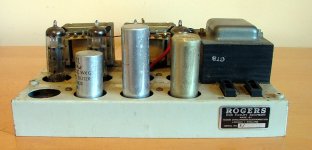
Rogers Cadet III stereo integrated amplifier
To date though i changed the small electrolytics and non electrolytics and various resistors.
IT works for a few seconds as you power it up then both channels fade and then a low level hum takes over, I have noticed that when it is switched on the DC supply is 355v this then starts to drop rapidly as the sound fades to about 235v then i switch it off, the resevoir caps are not physically leaking and they produce a healthy swing when i test them
I am not that experienced with valve amps and am at a loss now as to what to try next
Gary
I have a Cadet 3 power amplifier that was working, then one channel went down and started humming, then the other.
I downloaded a schematic from the web, but to date have not found any component to be faulty.
Rogers Cadet III stereo integrated amplifier
To date though i changed the small electrolytics and non electrolytics and various resistors.
IT works for a few seconds as you power it up then both channels fade and then a low level hum takes over, I have noticed that when it is switched on the DC supply is 355v this then starts to drop rapidly as the sound fades to about 235v then i switch it off, the resevoir caps are not physically leaking and they produce a healthy swing when i test them
I am not that experienced with valve amps and am at a loss now as to what to try next
Gary
zedrider, I have a Rogers Cadet 3 and have had various problems with it in the past (if you search the forum for threads I have started/posted on you will see what I mean). Similarly to you, I had tested many components and everything seemed fine. In the end, I decided to change every single passive component in the power amp stage as well as clean and resolder all connections and this solved every problem bar a very slight hum on the left channel (which I suspect relates to the amp being a 1960s budget model and the fact that the power tranny is right next to the left channel valves).
I would definitely change all power supply capacitors - leaving 30-40 year old electrolytics in your amp is not the best idea, particularly given how cheap they are to replace. You may find it hard to get original specification parts. For example mine had some impossible to find dual cans for C8 and C9 in the power amp section as well as C12 and C13 in the pre-amp section. No point wasting time and money sourcing this sort of thing - just replace them with whatever you can find easily. You may need to do some creative DIY to fix modern components to the chassis, but nothing too complicated.
I would definitely change all power supply capacitors - leaving 30-40 year old electrolytics in your amp is not the best idea, particularly given how cheap they are to replace. You may find it hard to get original specification parts. For example mine had some impossible to find dual cans for C8 and C9 in the power amp section as well as C12 and C13 in the pre-amp section. No point wasting time and money sourcing this sort of thing - just replace them with whatever you can find easily. You may need to do some creative DIY to fix modern components to the chassis, but nothing too complicated.
Hello Thanks to both of you for replying
I have checked all the resevoir caps and none of them are getting hot at all.
I take your point about changing the resevoir caps and be done with the old ones, i havent any that are suitable to hand, mine are all too high in capacitance.
I will however trawl ebay and see what i can find, mine has a 24uf 350v DC cap which the negative feeds into a 100uf on the power supply. So i presume this to be wrong as according to the schematic they should both be 100uf
I have spent a another few hours today checking the componants and scratching my head so at least if i change the old caps then that will remove them as the possible problem
There is one capacitor that puzzles me and that is C8 (16uf 350v DC) on my amp it doesnt exist, it is after R16 (5.6K) not a trace of it anywhere maybe this was a later detail alteration
Again thanks chaps for responding
GaRY
I have a Rogers Cadet III as well (I even have a couple of spare unobtainum ECC807 stashed).
I would suspect C6 the cathode bypass capacitor on the output tubes. Try replacing that first. There should be approx +10 to +12 volts across this cap if not, the cap is probably shorted.
If that is OK I would next check/replace C4 and C5, the coupling capacitors from the phase splitter. There should be NO DC voltage across R10 and R11, if there is anymore than say 0.1 volts across either resistor then it indicates C4 or C5 are leaky and need replacing.
C8 should exist - If it doesn't then add a 22uF/450V (350V would be OK) in the position shown on the schematic.
Never use 2nd hand or used Electrolytic capacitors - always buy new ones. Panasonic ED Series are what I would recommend. Get them from Farnell or similar supplier.
When I got my Cadet III about 5 years ago it was running OK BUT I still went in and replaced EVERY electrolytic cap in the unit. I did this for 2 reasons:
1. Electrolytics have a life of not more than 20 years and sometimes as little as 1/2 that, so it is something I do to any gear that is older than say 10 years.
2. The modern electrolytic caps are FAR superior to the ones that were being made 10 or more years ago.
Cheers,
Ian
Last edited:
I second gingertube's comment - C8 has to exist. Are you 100% certain it doesn't? in my Rogers C8 and C9 were in a single can (i.e. dual cap with common ground). As I said before, it's pretty hard to find such components these days and, as gingertube noted, getting second hand electrolytics is not a good idea and I would probably extend this to new-old-stock - passive components have come a long way over the last 50 years so do get modern replacements if you want the amp to run reliably.
You can find most of the components you need in farnell or RS. If you decide to replace the close tolerance polystyrene caps in the pre-amp EQ (some of mine looked fried), check this:
Rush-On-Line for polystyrene capacitors and capacitors of all types
Before replacing the power supply caps, check this thread, SY had some good advice on tweaking the values which worked for me:
http://www.diyaudio.com/forums/tubes-valves/158469-smoothing-caps.html
Finally, keep in mind also that the schematic you are looking at is the one for the "separates" version of the amp, whereas I suspect you have the integrated one. I found a handful of differences between the two, the power supply caps being one that springs to mind. I also seem to remember there was a difference in how the pre-amp valves were used - I think that instead of using one valve per channel for the first two stages, mine used both for both channels (i.e. one "half" of each valve for the left and one for the right), although my memory may fail me here...
Hello all again
Well firstly yes i must agree that the cicuit diagram is definatley different in the power supply section to my power amp.
first difference i have is C10/11, on mine it is a single 100uf cap, the negative then feeds the positive of C8 (yes it does exist, it is on my amp a 32+32 uf)..........the 470ohm resistor doesnt connect with it all?.
Then C9 is a 22 + 22 uf cap the 5.6K resistor goes across this one affectively?
these are the differences i have found, so today i partially tried the diagram way of wiring up the smoothing cap with two 220UF caps fuse/resistor feeding the mid point of the two caps, negative to ground and positive to the 470ohm and then to the positive of C8, well it didnt go bang it worked but the same problem exists.
The 100uf cap as i say shows no signs of being a dual can job so i am confused by it and the way it is wired.............
Does anyone have an alternate wiring diagram to the one i have ?
Again
Thanks to you all for your contributions and thoughts
Gary
I'm not sure I understand the last question correctly, but you can't replace two capacitors or a dual capacitor with a single one, unless for some bizarre reason the two are essentially wired in parallel (and in that case you need to consider capacitance value). Unless someone has messed around with the amp, this should not be the case in the Rogers. What you can do is replace the dual can with two single electrolytics.
I am also a little bit confused by your description. I would have expected C8 and C9 to be the two segments of the same dual can, with a 5.6k resistor across the positive poles, the common negative connected to the ground, the positive of C9 connected to C10 (with or without a resistor in series) and the positive of C8 "feeding" the two anodes (i.e. connected to pin 9 of the two output tubes through a load resistor). Is this not the case?
I would also expect the other double can to be C12 and C13 in the pre-amplifier and not in the power amp stage.
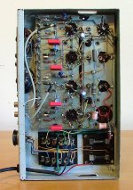
Finally, can I ask how many cans you can see in the amp? Mine has four (two single and two dual). Could you take some pictures (both bottom and top would be good), so that we can have a look?
I am also a little bit confused by your description. I would have expected C8 and C9 to be the two segments of the same dual can, with a 5.6k resistor across the positive poles, the common negative connected to the ground, the positive of C9 connected to C10 (with or without a resistor in series) and the positive of C8 "feeding" the two anodes (i.e. connected to pin 9 of the two output tubes through a load resistor). Is this not the case?
I would also expect the other double can to be C12 and C13 in the pre-amplifier and not in the power amp stage.
Finally, can I ask how many cans you can see in the amp? Mine has four (two single and two dual). Could you take some pictures (both bottom and top would be good), so that we can have a look?
Morning
I can only see three caps, the 100uf resevoir cap and the two dual caps,
What i will do is take some fots for you, I am working away today but am back tomorrow (friday) so will do them then.
Hmm maybe this is not a Cadet power amplifier i am now wondering, anyway thanks again and i will get back with some fots
Gary
Ps maybe my description of a Dual Can is wrong, in the 1970s Sony made big use of Dual Can caps in their Amplifiers and Receivers, they all had 3 connectors, -V 0 V+ for the split rail power supplies
First of all, my sincere apologies, I only just realised that you said in your first post that you have the power amplifier only and for some reason assumed you have the integrated version, which is essentially a pre and power in one chassis.
Please ignore everything I said about pre-amp capacitors. Also, ignore the comment about the four cans - t makes sense that you have three as the fourth one would be for powering the pre-amp in an integrated version.
Do take some pics and try to take some close-ups of the three capacitors, so we can try and figure out what is what. Having 3 pins does not necessarily mean a can is dual. Must admit I don't know what the -V 0 V+ cans are...the original dual caps on my power supply were essentially two capacitors in one can, with a common negative pole.
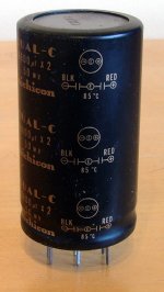
Whatever happens, I suggest you order a pair of 100uF, to replace C10 and C11, and a pair of anything from 16uF to 200uF to replace C8 and C9 (all these values should work, so chose depending on what you can find easily/price/whatever else rocks your boat).
While you are at it, I cannot recommend enough that you order replacements for the rest of the capacitors and ideally also all resistors. When I first got my Rogers I started fixing it using your de-bugging approach (i.e. gradually replacing individual components until I find what's wrong). After a few hapless weeks, I bit the bullet and replaced everything else and only then did it get back to working ok. In retrospect, had I done this from day one I'd have saved myself a fair amount of shipping costs for various components and at least three or four frustrating Sunday afternoons.
The vast majority of components you will need to do a complete re-vamp are available on uk.rs-online.com.
Please ignore everything I said about pre-amp capacitors. Also, ignore the comment about the four cans - t makes sense that you have three as the fourth one would be for powering the pre-amp in an integrated version.
Do take some pics and try to take some close-ups of the three capacitors, so we can try and figure out what is what. Having 3 pins does not necessarily mean a can is dual. Must admit I don't know what the -V 0 V+ cans are...the original dual caps on my power supply were essentially two capacitors in one can, with a common negative pole.
Whatever happens, I suggest you order a pair of 100uF, to replace C10 and C11, and a pair of anything from 16uF to 200uF to replace C8 and C9 (all these values should work, so chose depending on what you can find easily/price/whatever else rocks your boat).
While you are at it, I cannot recommend enough that you order replacements for the rest of the capacitors and ideally also all resistors. When I first got my Rogers I started fixing it using your de-bugging approach (i.e. gradually replacing individual components until I find what's wrong). After a few hapless weeks, I bit the bullet and replaced everything else and only then did it get back to working ok. In retrospect, had I done this from day one I'd have saved myself a fair amount of shipping costs for various components and at least three or four frustrating Sunday afternoons.
The vast majority of components you will need to do a complete re-vamp are available on uk.rs-online.com.

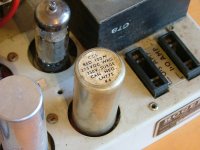
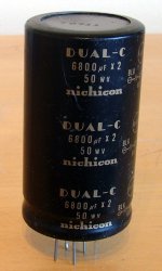
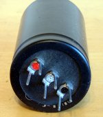
The 100uF is probably a dual 100uF. As with all older caps with non-insulated cans, the case is the negative, and the posts are the positives of each section. You can see negative lead (bare wire) joining each can's case under the chassis.
This applies to the 32+32uF and 24+24uF as well. So unless you can find similar dual cans to replace them, you will have to find a way to accommodate two capacitors for each dual can you replace.
JJ still market dual cans, but you would have to check the physical measurements to see if they will fit neatly (modern electros are much smaller than old ones).
Gary
The 100uF can is a single cap, whereas the 32+32 and 24+24 are duals. As I mentioned in an earlier post, you can treat them as two separate capacitors with a common negative node. As rotaspec noted, the negatives for the three cans are the outer cans themselves (and the outer "legs" that are attached to their bottom).
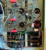
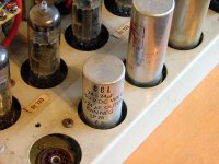
I have edited one of your pictures and have added pink circles to indicate the negative nodes for each of the three cans (note that each can has three, but this is irrelevant - they are all connected to the can so you can treat them as one node).
It is worth also mentioning that, although the 32+32 can is a dual capacitor, only one of the two "segments" is being used. Notice how only one of the two positive "legs" (the one marked red) is actually connected to anything.
Now, looking at the pictures against the schematic, I think that:
C10 is the 100uF can (the one with the plastic base)
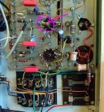
C11 is the part of the 32+32uF that is being used. Notice that its positive (the "leg" marked red) is connected to the negative of the 100uF. Its negative is soldered to the ground, where the back end of the MR2 diode is also soldered, in line with the schematic (the diodes seem to be the two deformed looking pink things, that are connected to the end of the yellow wire that goes into the transformer)
C8 and C9 are the two parts of the 24+24uF cap.
Does this make sense now?
I have edited one of your pictures and have added pink circles to indicate the negative nodes for each of the three cans (note that each can has three, but this is irrelevant - they are all connected to the can so you can treat them as one node).
It is worth also mentioning that, although the 32+32 can is a dual capacitor, only one of the two "segments" is being used. Notice how only one of the two positive "legs" (the one marked red) is actually connected to anything.
Now, looking at the pictures against the schematic, I think that:
C10 is the 100uF can (the one with the plastic base)
C11 is the part of the 32+32uF that is being used. Notice that its positive (the "leg" marked red) is connected to the negative of the 100uF. Its negative is soldered to the ground, where the back end of the MR2 diode is also soldered, in line with the schematic (the diodes seem to be the two deformed looking pink things, that are connected to the end of the yellow wire that goes into the transformer)
C8 and C9 are the two parts of the 24+24uF cap.
Does this make sense now?
Last edited:

Guys,
Just a couple of notes. If dual electrolytic can type caps need replacing it is often better to leave them in place, cut the connection to them, and use single units under the chassis as replacements.
If using replacement dual can caps, one of the 2 caps will be on the "outside" and one will be toward the Centre of the can. The outside one has better cooling and should always be used in the higher ripple current position which will be the one closer to the rectifier output.
That is for example:
Rectifier => Outside Cap => Dropping Resistor(or choke) => Inside Cap.
Cheers,
Ian
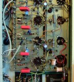
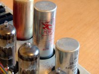
Ian, while we have you here, could you please have a look at the picture below and let me know if you have any idea what the circled part is? It's not in the schematic and it was originally also there in my Cadet. (When I overhauled it it I got rid of it and it works fine without it.)
Attachments
- Status
- This old topic is closed. If you want to reopen this topic, contact a moderator using the "Report Post" button.
- Home
- Amplifiers
- Tubes / Valves
- Rogers Cadet 3 Problem