I am confused about rectifier current and how to interpret PSUD.
I am using a GZ34 rectifier to a CLC to a PP amp drawing max 250mA.
My Transformer is 417V,2 x 150R to the rectifier, the first cap is 10u, inductor is 8H 50R, the second cap is 100u and the load is a current source at 250mA modeled in PSUD.
Simple, right? The actual cap values may change, but that is not the point.
The rectifier requires a transformer resistance of 2 x 125R, and the first cap cannot exceed 60u, so I have both of those parameters covered, yet PSUD tells me I have exceeded the current capability of the rectifier and the initial peak current is huge (under 1/2 second). Even after turn on, the ongoing chart per PSUD is a series of current peaks that exceed the rating of the rectifier. I couldn't begin to approach a 60u cap with out PSUD telling me I will blow up.
I do not know how to interpret this. The total current draw of 250 mA pushes the limits of the rectifier, but shouldn't the input resistance and first cap values protect against this current inrush killing my rectifier?
What am I doing wrong?
This happens to me quite a lot. Sometimes it is combinations of current sources and voltages that seem to not get along together. In this case, I usually try substituting a resistor instead of current source.
THe other way I get this error comes from not getting the cap prefix right. Check that the schematic really shows uF and not F!
If it still wont work, rename the file supply.txt and load it here & we'll try it!
THe other way I get this error comes from not getting the cap prefix right. Check that the schematic really shows uF and not F!
If it still wont work, rename the file supply.txt and load it here & we'll try it!
Thanks. I guess the real question is, if I know my transformer resistance and first capacitor are in spec per the tube data sheet, do I even need to worry about what PSUD tells me in regard to these current peaks, or should I ignore it and just use PSUD to model the other data?
In terms of my build, I may end up paralleling two GZ34s so i am not pushing the limits of the tubes anyway. For a PP like this, where I want to bias the EL34s around 50-60mA (x4 = 240mA) and need about 20-30mA more for the front end I probably should be using solid state, but i don't want to....
In terms of my build, I may end up paralleling two GZ34s so i am not pushing the limits of the tubes anyway. For a PP like this, where I want to bias the EL34s around 50-60mA (x4 = 240mA) and need about 20-30mA more for the front end I probably should be using solid state, but i don't want to....
I think it is well worth making it work, because you are near the top of the dc current range for GZ34. A lower 1st C will give you more margin on rectifier lifetime than 60uF. You can make up for the increased ripple by using a larger 2nd C.
The new production GZs have a patchy reliability record.
The new production GZs have a patchy reliability record.
I think it is well worth making it work, because you are near the top of the dc current range for GZ34. A lower 1st C will give you more margin on rectifier lifetime than 60uF. You can make up for the increased ripple by using a larger 2nd C.
The new production GZs have a patchy reliability record.
Hmmm, I am not too worried about ripple, the input stage will be regulated and the output should take care of normal stuff. But reliability and all, I think I will just parallel the tubes for the heck of it. It will bring my parameters way down per tube, decrease sag, look cool and allow easier rectifier tube rolling when my GZ34s crap out
")
Besides, I have got two....
I still don't really understand how to interpret PSUDs rectifier current information. How am I getting such huge peaks when I am within all the parameters of the rectifier? Either I don't understand and I should be looking at RMS values not peak or PSUD emulates incorrectly in this regard or the rectifier recommended values are not really that much protection.
I just modeled it based on your info above and did not get any warnings in PSUD, although 250ma seems to be pushing the envelope on the rectifier. I used 310R for the transformer R (150R X 2 plus 10R for windings-probably more severe than real life)
Seems like the RMS current value is not too bad.....
Seems like the RMS current value is not too bad.....
Attachments
Last edited:
I just modeled it based on your info above and did not get any warnings in PSUD, although 250ma seems to be pushing the envelope on the rectifier. I used 310R for the transformer R (150R X 2 plus 10R for windings-probably more severe than real life)
Seems like the RMS current value is not too bad.....
Yes, but the model for the transformer is 50R (this is a calculated impedance from PSUD's calculator) for the transformer and adding 100R before each plate of the rectifier. This actually models as 150R, not 310R. I can't recall where I read to do it that way, but I did. Is it wrong? I will try to look it up again.
I can add more resistance to reduce the current load, but then I reduce my B+ too much. I want around 430V.
I am getting the impression that the transient peaks in PSUD are something to worry about and if I want my B+ where I want it and my current too, I need to parallel rectifiers.
Are you aiming for class AB? If so keep in mind the current is more like 4 x 140mA at full power (425V B+) if the bias is 4x 50mA
I am actually aiming for class A.
But well taken, I may want to parallel rectifiers anyway to make sure I have plenty of headroom.
Yes, but the model for the transformer is 50R (this is a calculated impedance from PSUD's calculator) for the transformer and adding 100R before each plate of the rectifier. This actually models as 150R, not 310R. I can't recall where I read to do it that way, but I did. Is it wrong? I will try to look it up again.
I can add more resistance to reduce the current load, but then I reduce my B+ too much. I want around 430V.
I am getting the impression that the transient peaks in PSUD are something to worry about and if I want my B+ where I want it and my current too, I need to parallel rectifiers.
If you are putting 100R before each rectifier plate, and PSUD calculates the transformer R at 50 ohms, then it seems like the composite R should be 250R in the model.......
That looks like it will get you no more than 375V or so B+ with your existing transformer.
I had a similar struggle trying to use a 5AR4 for a stereo PP EL34 amp @ 50ma/tube, and ended up with SS rectification.
I will try to find my reference for doing it my way when I have time (working, but would rather think about this...
), but I may well be wrong. In any case, it looks like I can't get this system to work safely at these current requirements. This amp is going to pull too much for the voltage I want, so I either have to redesign to use a lower B+, lower bias current, go SS, blow up my rectifier
, or parallel the rectifier. I think I will parallel because I am stuck on the idea of valve rectification for this amp. Parallel will make all these issues go away.
Are you aiming for class AB? If so keep in mind the current is more like 4 x 140mA at full power (425V B+) if the bias is 4x 50mA
That's AB,Whatis it for class A only?
Strict class A: the max current = the bias current, 4x50mA. The power output would be quite low....
Chris's suggestion of the CL140 inrush limiter is worth adopting - especially with recent GZ34s
Thanks, and thanks Chris. It sounds good to have something to protect these tubes, especially the JJ's I have, based on other comments.
I am hoping to get about 14-16W class A, which should be ample for me. The EL34s will be true triode strapped and I think I will actually go for parallel rectifiers to reduce sag and allow a slightly higher operating voltage as well as more current safety margin. I have 4 GZ34's, two JJ and 2 shanguan, a bunch of UF4007's and think I even have the CL140s. so why the heck not.
If I want a little more power, the circuit should be flexible enough to run into AB1 at the top and if I really need to I could go UL with a few minor changes.
Any considerations to parallel rectifier tubes? I have been researching, but can't find a lot. They are in a few schematics simply paralleled, but I have also seen references to series resistors to balance the tube currents. Is anything like that necessary? There will be a lot of headroom for each tube regardless.
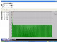
If I understand correctly you have a current peak at start up that violates the max current for the rectifier.
This current peak is only "on paper". In actuality the current through the output tubes will not ramp up for several seconds. The way to model this is to use the current step feature offered by PSUD. Click on stepped load. Add value 1 at maybe 2mA then add Value 2 at your expected current draw say 248mA after 2 second so you total is the 250mA.
By using the stepped current feature gives a much more accurate view of the way the amp actually powers up. If you want to be really accurate, time the actual time to current draw of the tubes in your model. Don't forget to do this for all the stages as the driver and voltage amp tubes do not conduct instantaneously either (neither does the rectifier). I think you will find that your PS will be fine and your rectifier tube will not be stressed at all.
If I understand correctly you have a current peak at start up that violates the max current for the rectifier.
This current peak is only "on paper". In actuality the current through the output tubes will not ramp up for several seconds. The way to model this is to use the current step feature offered by PSUD. Click on stepped load. Add value 1 at maybe 2mA then add Value 2 at your expected current draw say 248mA after 2 second so you total is the 250mA.
By using the stepped current feature gives a much more accurate view of the way the amp actually powers up. If you want to be really accurate, time the actual time to current draw of the tubes in your model. Don't forget to do this for all the stages as the driver and voltage amp tubes do not conduct instantaneously either (neither does the rectifier). I think you will find that your PS will be fine and your rectifier tube will not be stressed at all.
Thanks, that is helpful. Do you think my plan to parallel rectifiers is overkill then? The minimal draw in class A will be 240ma, if I enter class AB1, the current may rise significantly and the GZ34 is only rated at 250ma continuously. Seems like sag, lower voltage and risky lack of headroom, so a second rectifier is easy if there are no significant disadvantages. I have the tube, socket and enough filament current available.
I would ditch the GZ34 for the better sounding and cheaper 5AU4/5V3 or the 5V3A. You get over 1 amp PER PLATE. These rectifiers are $10 - $15 on eBay and sound at least as good as the mid 1960s GZ34. The only caution is that the 5AU4/5V3 requires 3.8A current and the 5V3A requires 3A. So the 5V3A can be substituted for a 5U4. There were a couple on eBay for $8 recently and may still be there. The GZ34s look like toys compared to the 5AU4/5V3A. They are about the same size as a 6550.
I would ditch the GZ34 for the better sounding and cheaper 5AU4/5V3 or the 5V3A. You get over 1 amp PER PLATE. These rectifiers are $10 - $15 on eBay and sound at least as good as the mid 1960s GZ34. The only caution is that the 5AU4/5V3 requires 3.8A current and the 5V3A requires 3A. So the 5V3A can be substituted for a 5U4. There were a couple on eBay for $8 recently and may still be there. The GZ34s look like toys compared to the 5AU4/5V3A. They are about the same size as a 6550.
Sounds like an option and could be a drop in, even dropping in one in place of 2 GZ34s, but a much greater voltage drop that may put me out of my preferred operating range. I'll model it and see, and at that price, may just try it for kicks. That's how we learn after all.
Side question, how to make a load to test the power supply at near operating conditions before I have connected to the amplifier in case I am about to fry something. A mock load need a few kohms and 100W...
- Status
- This old topic is closed. If you want to reopen this topic, contact a moderator using the "Report Post" button.
- Home
- Amplifiers
- Tubes / Valves
- valve rectifier in PSUD