Hello,
I just purchased this to build a 45 SET (see pic). The schematic on the side of this transformer shows a center tap but it does not designate which pin is actually the CT. In fact there are 10 pinouts on the bottom, all of which are accounted for on the schematic, none of which are shown to be the CT. There are no other pinouts anywhere on the transformer??? So where is the CT shown on the schematic???
Help!!!
Jeff
Last edited:
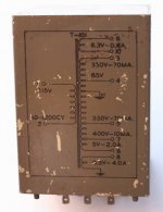
Another question, how do I use the 5V winding since it appears to be a part of the other windings? Or is it actually a seperate winding?
You can use it for a negative supply... only 10 mA rating, though...
There's an extra 6V winding - use it for a 6X5.
You can use it for a negative supply... only 10 mA rating, though...
There's an extra 6V winding - use it for a 6X5.
It appears the 5V is a 2 amp rating, I think you might be referring to the other voltage, the 400V @10mA.
The 5 volt winding is connected to the 400 volt winding. All of the common 5 volt rectifier tubes have their 5 volt heaters (or filaments) connected directly to the cathode. This means that in order to use the 5 volt winding you are connecting the 400 volt tap to the cathode of the tube which will result in a negative voltage supply. This was not too uncommon in some millitary display applications including small oscilloscopes.
The usual trick of grounding the plates and taking the positive B+ output from the center tap won't work here since you will get 400 volts on the transformer case.
It does appear that to use this transformer you will need to use a 6 volt rectifier tube like the 6X4 or 6X5 to get a positive supply voltage.
- Status
- This old topic is closed. If you want to reopen this topic, contact a moderator using the "Report Post" button.
- Home
- Amplifiers
- Tubes / Valves
- Help figuring which is the center tap???