Yes you are correct of course. I knew that. But just wanted to demonstrate clearly the branching after the choke.")
Problem is, it doesn't demonstrate the correct outcome, and it doesn't properly represent the branching. To accomplish both, it would be better to model as summed parallel branches, and have a separate (not in PSUD) schematic. This applies to parallel chokes too (which would be modeled as 1/2 the value).
BTW, if you add series resistance as shown, and it is followed by a good sized cap, your supply impedance will be largely determined by the final cap, providing it big enough to deliver current at all audio frequencies. Film cap should go there if you've got a good sized one.
Sheldon
Last edited:
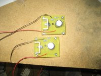
Film caps all round. 2uF is Obbligato pp in oil. Second one 60uF is a Pirelli motor start. Last 2 for each channel ASC pp in oil 40uF.Film cap should go there.
BTW, if you add series resistance as shown, and it is followed by a good sized cap, your supply impedance will be largely determined by the final cap, providing it's big enough to deliver current at all audio frequencies.
Sheldon
Never thought of it that way......good to know.........So if the final cap can provide the juice, the PS output impedance is essentially the ESR of the final cap? How do you know when it's big enough?
Never thought of it that way......good to know.........So if the final cap can provide the juice, the PS output impedance is essentially the ESR of the final cap? How do you know when it's big enough?
Good question. The best way to do that without the math background would be to model it in spice.
But I think you can look at it like any other RC circuit. Consider the final supply cap and the following impedance to form a high pass filter. Simplifying: the reflected load through the transformer would represent R in the high pass circuit. So if your transformer is 5k, and your final cap is 40uF, the -3dB point would be around 1Hz. But that's about 37% ripple. Of course, at 20Hz it will be much lower, so I'm guessing that it's in a good ballpark, but I'm not sure of the correct way to calculate the ripple at that frequency. And the preceding resistor and circuit will interact, as will variations in speaker impedance. Maybe someone can come up with a good rule of thumb. But even if it's simmed, you still need to decide how much ripple is acceptable.
Sheldon
Well, Edcor said they would not be able to ship transformers for eight weeks, so I called Jack Eliano and, after learning he no longer answers the phone, I E-mailed him.
He really hates telemarketers.
He's in the process of winding the power and output transformers, which is exciting.
More to come...
Kofi
He really hates telemarketers.
He's in the process of winding the power and output transformers, which is exciting.
More to come...
Kofi
Sounds interesting Kofi. I have had my Baby Huey for a while now with the Edcor output transformers. I am in the process of building a pair of PP 6L6 amps with Tamura output iron. I have my speakers set up with active crossovers, so when I put my 6L6 amps in the system I am either going to ditch the active crossover and have the new amps power the both drivers, or tweak the Baby Huey for tweeter duty. For this purpose I was thinking of upgrading the output transformers, so would be very interested in the specification you ordered through electra-print and if you are able to, an indication of the price.
Regards,
Chris
Regards,
Chris
...would be very interested in the specification you ordered through electra-print and if you are able to, an indication of the price.
Regards,
Chris
Sure.
OPT: 100mA / 44% UL taps / 8K primary / 8-ohm secondary / 15W / $115.00 each plus shipping
Power: 200mA / 275-0-275 / 5V @ 3A / 6.3V @ 6A / $130.00 for M19 laminations, $172.00 for M6 (M6 runs cooler, according to Jack).
Hope this helps.
Kofi
You will like Jack's iron.
Indeed. His iron is in all of my projects for the last three years.
Kofi
Sure.
OPT: 100mA / 44% UL taps / 8K primary / 8-ohm secondary / 15W / $115.00 each plus shipping
Power: 200mA / 275-0-275 / 5V @ 3A / 6.3V @ 6A / $130.00 for M19 laminations, $172.00 for M6 (M6 runs cooler, according to Jack).
Hope this helps.
Kofi
Thanks for the info Kofi. Hope your project goes well!
Chris
Got some 20K resistors, so I'll use those...
I know its been a while, but the top plate is now dry and I'm ready to start the serious soldering.
First question of the day-- what's the best way to test the bias blocks and CCSssessses? Can i put a resistor across them and test before they come in contact with the rest of the circuit? If so, what value resistor would be best?
Pictures coming...
Kofi
Anyone?
Kofi: Gingertube covers testing the blocks in posts #402/#403 of the original BH thread.
http://www.diyaudio.com/forums/tubes-valves/72536-el84-amp-baby-huey-9.html
AAARRRGGGGHHH!!!!
So, I was clipping a lead today on the PSU side and the little bastard bounced around the chassis top and went into the MOTHERFATHER HOLE in the MOTHERFATHER TRANNY on the primary side.
Anyone got any good ideas on how to get this out? Do I need to pull the transformer apart or can I sigh it out somehow?
FFFUUUUDDDGGGGEEE!!!
KKKOOOFFFIII!!!
- Status
- This old topic is closed. If you want to reopen this topic, contact a moderator using the "Report Post" button.
- Home
- Amplifiers
- Tubes / Valves
- Kofi Annan in: "Kofi's Baby Huey"