Hey guys,
I've been posting over at diytube, but I'd like to put this out here too. Here's my latest design. Please give me any feedback (negative or positive) on this circuit. Thanks!
Kyle
I've been posting over at diytube, but I'd like to put this out here too. Here's my latest design. Please give me any feedback (negative or positive) on this circuit. Thanks!
An externally hosted image should be here but it was not working when we last tested it.
Kyle
Hey guys,
I've been posting over at diytube, but I'd like to put this out here too. Here's my latest design. Please give me any feedback (negative or positive) on this circuit. Thanks!
Kyle
You need floating grid drive on A and D
I assume the 6SN7 is for example and you're not planning on building a power amp with a single 6SN7 bridge ;-)
Michael
Last edited:
What do you mean, float the grids? I'm still relatively new to tube audio, but I know it's superior! ")
I actually was planning on using 6SN7s to drive some headphones. I bought some Sennheiser HD-555s which I am quite happy with. I have some pretty good iron, although I am not sure if they will match the impedance of the circuit. (How can I determine that?) They are UTCs with 15K primaries and 50 to 500 ohm secondaries. Right now they are hooked up to another 6SN7 headphone amp, but they can be easily taken out.
I suppose this would be an appropriate design for some power tubes as well. Maybe some EL84s? Either way, I think the 6SN7 should be a good "proof-of-concept" for this circuit.
Thanks for the tips!
Kyle
What do you mean, float the grids? I'm still relatively new to tube audio, but I know it's superior!
I actually was planning on using 6SN7s to drive some headphones. I bought some Sennheiser HD-555s which I am quite happy with. I have some pretty good iron, although I am not sure if they will match the impedance of the circuit. (How can I determine that?) They are UTCs with 15K primaries and 50 to 500 ohm secondaries. Right now they are hooked up to another 6SN7 headphone amp, but they can be easily taken out.
I suppose this would be an appropriate design for some power tubes as well. Maybe some EL84s? Either way, I think the 6SN7 should be a good "proof-of-concept" for this circuit.
Thanks for the tips!
Kyle
Your idea is interesting. First I'll explain why I think floating drive is needed.
I assume your intent is to have the diagonal tubes e.g. A and B to both increase conduction together while C and D both decrease together.
However, B and C will reach their limits of conduction (assuming class A operation) at about 10 volts peak signal relative to their cathodes, which are at ground potential.
Let's assume B is being driven positive while C is driven negative. Driving B 10 volts positive causes tube B to increase conduction to let's say 20mA (depending on the load). At the same time, D is driven 10 volts negative with respect to ground, resulting in a current *increase* in D as B's plate tries to swing lower than 10 volts below quiescent.
If you want balanced complementary current swings, you need to drive the grids of A and D with balanced complementary relative to their cathodes instead of relative to ground. I think a small line transformer for each side would do the trick.
Edit: Probably would need a lower impedance drive circuit for transformers but you get the idea.
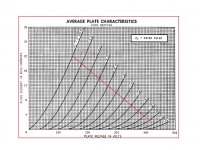
The next question is load impedance. The 6SN7 will autobias at about 10mA with the 1K resistors with the 600V supply split between top and bottom. If you do drive the top and bottom with complementary grid-cathode signals, they will work effectively in parallel and will present about 4K ohms source impedance to each side of the transformer. Your 15K primary if loaded with the matching secondary load will present 7K5 to each side, giving a dampling factor approaching 2, which should be great for headphones.
Each 6SN7 will see a 15K ohm load line, swinging ~260V pk-pk per side. That's 180V rms into 15K. I take it back about the 6SN7s, you should get about 2 watts power output! Enough to drive any headphones and even LaScalas.
I think the whole thing's pretty viable if you transformer couple your A and D signals with the secondaries between cathode and grid.
Cheers,
Michael
PS I am assuming also cathode bypass in the above estimate of the damping factor. With unbypassed cathode resistors, it will take about 2X the drive voltage ant the output impedance will be much higher. It still might be a great headphone amp without the cathode bypass.
Attachments
Last edited:
You need two of these:
http://webpages.charter.net/dawill/tmoranwms/Circuits_2010/Tube_Half_Bridge.png
http://webpages.charter.net/dawill/tmoranwms/Circuits_2010/Tube_Half_Bridge.png
I have a few more comments:
Upper tube grid drive wrt it's cathode: Broskie wrote up a similar idea but I can't find it right now. I believe he showed a phase splitting transformer driving a half bridge but he called it something else, can't recall...
There may be another way to bootstrap the upper grid drive; maybe there's some idea in Tim's Sch3mat1c of the class D half-bridge that I'm not seeing applied to an analog gain circuit. Some clever adaptation of N-device totem poles ala JLH perhaps. Lots of circuits out there to study.
The heaters for the upper tubes will need separate transformers to avoid exceeding maximum Vhk. I would connect each heater to it's respective cathode and use split bobbin filament transformers to reduce capacitive loading and potential Vhk excursions.
I understand you want to drive the upper grids but you might consider trying SRPP also and comparing the results. It should be easy to modify the circuit.
Cheers,
Michael
I think I've taken care of the heater problems. Check out the bottom right corner. I've attached the centertap of the top 6SN7's filament line to +300V. That should take care of the Vhk risk. I have tons of 240V-12.6V transformers which happen to work great with 120V on the primaries!
I found this...and the grounded cathode totem pole and the cathode follower totem pole. I think this is exactly what I was envisioning. This mid-referenced totem pole seems like a true winner, although I am not crazy about the split B+ supply. I think I might have a solution, and that would be to feed the 600V to the B+ of the 6SL7 phase splitter and 300V to the "ground" of the splitter. That way it should be referenced correctly.
I'm still working on building a prototype of it right now, but once I have it done, I should be able to do plenty of experimentation. I'll definitely post my results when I get them!
Kyle
Hey guys,
Tell me what you think of my latest design. It is similar in thought to the mid-referenced design here: Mid-Referenced Totem Pole Amplifier
Kyle
Tell me what you think of my latest design. It is similar in thought to the mid-referenced design here: Mid-Referenced Totem Pole Amplifier
An externally hosted image should be here but it was not working when we last tested it.
Kyle
Hi KyleTell me what you think of my latest design.
It has the same basic problem as the original circuit. For it to work properly, the grids of the top left tube and bottom right tube must not be driven with the same AC voltage. Same story for the other two.
You do want the same "input voltage" for each of the output tubes. However, each tube's "input voltage" is the voltage between it's grid and it's cathode, not the voltage between it's grid and earth.
The cathodes of the upper tubes have the full output AC voltage on them, so the voltage on their grids needs to be that plus the input voltage.
Rolf had the same kind of problems getting his Accordian amplifier to work in this thread. Maybe reading through that will give a better idea of what the issues are.
btw, I think the Accordian amplifier is the Broskie circuit Michael was referring to in post 6 above.
Cheers - Godfrey
For example, notice in my circuit the top tube is pulled up to +V (in fact, slightly above +V, because the grid is supplied from the bootstrapped screen supply), while the bottom tube is merely driven with the regular input signal (which might be 100Vp-p). For a 1000V supply, that's more than 10 times the voltage swing at the top tube!
This approach could be linearized, making the gain stage pentode into a current source, which draws from a grid-cathode resistor on the top tube (not the bootstrap supply -- don't need that much grid drive for linear operation). Because it's a constant current drawing from a point referenced to the tube, the grid voltage seen by the top tube is no longer dependent on the cathode voltage, i.e. it's a regular tube now, not a cathode follower. That fixes that.
The tricky part is making it linear again, and figuring out how to drive both tubes so they are balanced, yet seperated to allow class AB operation.
Tim
Alright, I thought grounding the centertap of the transformer would allow me to use the same voltage on the inputs. I forgot that in order to have it mid-referenced like this:
I would need the resistors that go from the middle of the B+/B- supply to the middle of the two tubes.
Anyways...now that this circuit is mid-balanced, if I understand this correctly, it should now work with the same voltage inputs. Is this correct?
With that said, here's my latest revision:
Kyle
An externally hosted image should be here but it was not working when we last tested it.
I would need the resistors that go from the middle of the B+/B- supply to the middle of the two tubes.
Anyways...now that this circuit is mid-balanced, if I understand this correctly, it should now work with the same voltage inputs. Is this correct?
With that said, here's my latest revision:
An externally hosted image should be here but it was not working when we last tested it.
Kyle
Thing is, 5k isn't going to hold much sway over what your power supply is doing. Above 5kHz or so, capacitance in the power transformer, between B+ winding and shield (or worse yet, primary) will dominate. Better to have fixed supplies and make the tubes move. Tubes have less capacitance, and it's only to the heater winding, which is easier to isolate.
Also, I'm not sure if you intended to have the preamp/splitter tube also on this floating supply.
Anyways, it's easier to just drive them floating-style.
Notice the linearity is probably bad, since the 6L6s saturate (Vg = 0) when the 6AU6s cut off (Ip = 0, even with lots of cathode degeneration), and the output tubes should be matched (the 6AU6s could be matched as well, but the degeneration makes that less of a problem). There should be plenty of gain, so adding NFB is no problem with the explicitly differential input.
Plate, grid divider and cathode resistors are "left as an exercise for the student" (aka: the author is too lazy to do loadlines today).
Offhand, I would guess this circuit can do full power out to 500kHz without too much work (maybe some cathode "peaking" caps, smaller load resistors, higher Gm tubes). With damper diodes and screen grid protection, it could drive reactive loads quite well (lowfer class B linear, anyone?).
Tim
Also, I'm not sure if you intended to have the preamp/splitter tube also on this floating supply.
Anyways, it's easier to just drive them floating-style.
An externally hosted image should be here but it was not working when we last tested it.
Notice the linearity is probably bad, since the 6L6s saturate (Vg = 0) when the 6AU6s cut off (Ip = 0, even with lots of cathode degeneration), and the output tubes should be matched (the 6AU6s could be matched as well, but the degeneration makes that less of a problem). There should be plenty of gain, so adding NFB is no problem with the explicitly differential input.
Plate, grid divider and cathode resistors are "left as an exercise for the student" (aka: the author is too lazy to do loadlines today).
Offhand, I would guess this circuit can do full power out to 500kHz without too much work (maybe some cathode "peaking" caps, smaller load resistors, higher Gm tubes). With damper diodes and screen grid protection, it could drive reactive loads quite well (lowfer class B linear, anyone?).
Tim
- Status
- This old topic is closed. If you want to reopen this topic, contact a moderator using the "Report Post" button.
- Home
- Amplifiers
- Tubes / Valves
- H-Bridge Amp Design