I'm not the first to do this sort of thing or anything, but I threw together a circuit here with some analysis to stimulate some discussion and hopefully help me learn some more.
The attached circuit uses a p-channel mosfet follower with a so-called 'Schade network' to introduce plate-grid feedback and make the pentode or beam tetrode output tube behave like a very efficient low-mu triode. I put in an n-channel follower to present a very low capacitance to the Schade network. This allows higher resistances to be used in the Schade network without rolling off the high end too much. I have been using FQPF2N90(900V, 5.5pF Crss). Another advantage is that the driver can supply grid current. Anyway, the schematic shows values for 20% plate-grid feedback. I calculated out a 170+kHz corner frequency for the feedback network which should keep things nice and flat through the audio range.
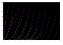
I have also attached curves for KT88 triode connected(blue), 300B(yellow), and KT88 with 20% plate-grid feedback (pink). Sorry, grid voltages are not labeled and are different increments for each of the three. If I recall correctly mu came out to a little less than 4 for the 300B, 5 for the plate-grid feedback KT88, and about 8 for triode connected KT88.
Anyway, I think that this circuit should best a 300B in linearity, gain, have a higher input impedance, lower plate resistance, and higher power output. It obviously has the disadvantage of needing a bunch of supply voltages, but I'm not gonna let that stop me.
Problems:
I am concerned about voltage ratings of p-channel devices. Maybe some protection circuit is in order? It shouldn't be a problem unless funky stuff happens on power up/down or oscillations or something.
Anybody see anything here that won't work or that I did wrong?
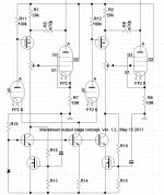
The attached circuit uses a p-channel mosfet follower with a so-called 'Schade network' to introduce plate-grid feedback and make the pentode or beam tetrode output tube behave like a very efficient low-mu triode. I put in an n-channel follower to present a very low capacitance to the Schade network. This allows higher resistances to be used in the Schade network without rolling off the high end too much. I have been using FQPF2N90(900V, 5.5pF Crss). Another advantage is that the driver can supply grid current. Anyway, the schematic shows values for 20% plate-grid feedback. I calculated out a 170+kHz corner frequency for the feedback network which should keep things nice and flat through the audio range.
I have also attached curves for KT88 triode connected(blue), 300B(yellow), and KT88 with 20% plate-grid feedback (pink). Sorry, grid voltages are not labeled and are different increments for each of the three. If I recall correctly mu came out to a little less than 4 for the 300B, 5 for the plate-grid feedback KT88, and about 8 for triode connected KT88.
Anyway, I think that this circuit should best a 300B in linearity, gain, have a higher input impedance, lower plate resistance, and higher power output. It obviously has the disadvantage of needing a bunch of supply voltages, but I'm not gonna let that stop me.
Problems:
I am concerned about voltage ratings of p-channel devices. Maybe some protection circuit is in order? It shouldn't be a problem unless funky stuff happens on power up/down or oscillations or something.
Anybody see anything here that won't work or that I did wrong?
Attachments
With DC coupling, the downside is a dramatic shift in cutoff bias. Instead of driving in the 0 to -60V range, say, you need -50 to -150 or more. The reduced input impedance demands heavy drive, such as the follower. All these followers brings the question, is it more "FET follower" sound than "tube" sound, if any at all? (The latter is the correct answer, of course, since NFB removes "sound".)
MOS will be happy up to 70% of rated. More than that and you're risking transients (line and load variation, inductive kick for switching circuits, etc.). At these currents, avalanche shouldn't really be harmful, so you could supply a narrowly rated FET from higher voltage than the operating point, as long as it doesn't stay there forever. I make no guarantees on this, of course...
If you can't find HV PMOS, you can cascode them.
Tim
From looking at the purple curves, it certainly looks like a very linear triode. A cascode could fix the P-chan voltage issue, but getting into a lot of parts then. I can see Tim's issue with the input follower causing some Fet characteristic, but not much due to it's high gm.
I like a little different approach to Schade feedback, using voltage or series feedback at the input. (see attached) Then the Fet operates at near or at constant current, so no Fet signature remaining (constant voltage across the Fet gate to source). Loses some voltage gain though, but tubes are good at voltage gain anyway. Some issue maybe with Drain to Gate capacitiance, but recent Fets are very good there if you keep 25 Volts or more across them. Main issue is tube bias stability, needs additional circuitry.
The super triode is a different animal, but a very nice scheme. Using the Fet for current gain and the tube for voltage gain control (via plate feedback) . With no Fet signature remaining either. Some Japanese sites have used that scheme for some time. You won't have much of any showy power tubes that way in most cases since the Fet is handling the power.
Attachments
Last edited:
JRB's "Super Triode" uses a vacuum tube to control a MOSFET, which is a sort of signal current multiplier (or conversely an impedance multiplier as seen by the tube). The end characteristic should be like rescaling the current axis of the plate curve of the controlling triode.
The Schade feedback scheme presented above uses a P-MOSFET follower to drive a vacuum tube with a "Schade network" feedback divider. It looks like a nice circuit for varying the % of feedback and hence the output impedance as desired. The triode characteristic is derived from the pentode gm and external feedback. The end characteristic will be similar to a very high gm triode spud amp.
Michael
would any of what you're presenting be related to this?
SuperTriode
Gee, that looks vaguely familliar. My web page is 5 years old:
Super Tubes
Japanese sites have used that scheme for some time. You won't have much of any showy power tubes that way in most cases since the Fet is handling the power.
My best sounding version used a 6W6 connected to a mosfet in a Simple SE board. Real tubes (6V6 sized) and a BIG heat sink on the fets. B+ was 150 volts and the power is limited by the OPT and the heat sink.
A couple of questions:
What does a cascode follower look like?
I think that the p-channel follower would be going from abut .5 to 6mA on the extremes. I would hope that what Vgs variation there is would be pretty small especially compared to the swings we are talking about here (100Vrms or so). Would there be a significant amount of distortion because of this? I don't know. I think I will eventually build this and see.
Don,
I'm going to have to take your drawings to work tomorrow and think about them a bit. How will these do as far as input capacitance? One of my design goals with this was to keep input impedance high so as to be easily driven by tubes.
How did your best version stack up soundwise against say a conventional se amp......Is it worth it in otherwords or does it sound like sand?
The experiments that I performed sounded quite tube like. The sound quality was limited by the budget pair of used Chinese "50 watt 600 ohm OPT's" that I was using. I found that the trioded 6W6 - mosfet pair and the paralelled sections of a 6336A sounded much the same except the 6W6 combo had more gain. The real power rating of the OPT's is about 10 watts and both combinations could easilly saturate the OPT's. More power from either combo could be achieved by a lower impedance OPT, which I don't have.
The P channel cascoded follower is attached. The Rd/Rd voltage divider keeps half the Source to Drain V drop on each Mosfet.
Edit: OOPs! I just noticed I drew an N-chan cascoded follower with P-chan parts. For P-chan, the divider middle would go to the bottom gate, and the input drive to the top gate. And sources go on the top sides.
I just noticed some goofs on my earlier diagrams. The bottom one should have the "or CCS" on the top drain resistor, not the bottom source one.
I forgot to put real in Mosfet diagrams too (my shorthand instead). Top diagram is P-chan and the bottom one N-chan. Some gate stoppers needed too.
With a CCS instead of a resistor in the above diagrams, the gate to source voltage stays near constant, so removing that capacitance issue (390pF for FQP2N90). The reverse transfer capacitance from drain to gate with Miller gain factor is now the predominant issue. (5.5 pF * Miller for FQP2N90) For the N-chan case, one could just use some 5W video amp tube instead.
The local loop gain gets quite high with the CCS's also, so some freq. roll-off element may be required for stability.
Attachments
Last edited:
Hey Spreadspectrum,
About the circuit in your first post, is the purpose to get rid of the capacitor between R18 and the OPT? Seems a little akward as the gate of Q3 should now be at something like -170V.
I see your point of adding Q4 to be able to run A2. If that isn´t necessary one could as well skip it and and only run a NMOS before the Schade network. That is if a triode driver is called for. I remember we discussed that one in the ECL86/Schade thread.
Did a simple sim with one NMOS-follower/Schade39k-150k/KT88 and it indicated -3dB at ca 350kHz. But then we need to have a coupling-cap before the KT88 grid.
Hey Spreadspectrum,
About the circuit in your first post, is the purpose to get rid of the capacitor between R18 and the OPT? Seems a little akward as the gate of Q3 should now be at something like -170V.
I see your point of adding Q4 to be able to run A2. If that isn´t necessary one could as well skip it and and only run a NMOS before the Schade network. That is if a triode driver is called for. I remember we discussed that one in the ECL86/Schade thread.
Did a simple sim with one NMOS-follower/Schade39k-150k/KT88 and it indicated -3dB at ca 350kHz. But then we need to have a coupling-cap before the KT88 grid.
Sorry I haven't posted in a while, my internet connection got cut off for a while there thanks to Verizon being too big to know what they are doing.
Lars,
Let me explain how I arrived at this circuit. I like running source followers to drive power tube grids. They present a tiny load to the previous stage which is great if you have a CCS loaded stage swinging a lot of volts. They also have no problem driving the grid positive if I want to, which I do for some strange reason. I already have hundreds of negative volts hanging around for the source follower, so I am not concerned that the gate of Q3 is -170 or so.
I had looked at using NMOS for both fets and using a capacitor but it seemed that this offered fewer parts and the opportunity to up the resistance values for the feedback resistors
The basic problem with the dual NMOS approach was that an NMOS Q3 would need a separate source resistor as the DC load. The feedback network would just be an AC load. The source resistor needs to be much lower (in numerical value) than the AC load of the feedback network so that you can deliver large voltage swings (necessary) with low distortion. Alternatively, you can make the values of the feedback resistors high but this will restrict bandwidth.
The PMOS approach offers the opportunity to use the feedback network as the source load resistor and eliminate the cap.
As far as your sim goes, I don't like the idea of a cap that can cause bias shift on clipping. That seems like a lot of bandwidth. I was calculating about 200kHz for the circuit in my first post, although I was having difficulty deriving an expression for the HF cutoff. I finally settled on F = 1/(2*PI*R18*Q4Crss). Is that right?
I'm not the first to do this sort of thing or anything, but I threw together a circuit here with some analysis to stimulate some discussion and hopefully help me learn some more.
The attached circuit uses a p-channel mosfet follower with a so-called 'Schade network' to introduce plate-grid feedback and make the pentode or beam tetrode output tube behave like a very efficient low-mu triode. I put in an n-channel follower to present a very low capacitance to the Schade network. This allows higher resistances to be used in the Schade network without rolling off the high end too much. I have been using FQPF2N90(900V, 5.5pF Crss). Another advantage is that the driver can supply grid current. Anyway, the schematic shows values for 20% plate-grid feedback. I calculated out a 170+kHz corner frequency for the feedback network which should keep things nice and flat through the audio range.
I have also attached curves for KT88 triode connected(blue), 300B(yellow), and KT88 with 20% plate-grid feedback (pink). Sorry, grid voltages are not labeled and are different increments for each of the three. If I recall correctly mu came out to a little less than 4 for the 300B, 5 for the plate-grid feedback KT88, and about 8 for triode connected KT88.
Anyway, I think that this circuit should best a 300B in linearity, gain, have a higher input impedance, lower plate resistance, and higher power output. It obviously has the disadvantage of needing a bunch of supply voltages, but I'm not gonna let that stop me.
Problems:
I am concerned about voltage ratings of p-channel devices. Maybe some protection circuit is in order? It shouldn't be a problem unless funky stuff happens on power up/down or oscillations or something.
Anybody see anything here that won't work or that I did wrong?
I think your circuit is worth a try as it is. I don't see any of the concerns so far as being any problem.
The bias volatage should be about -30 assuming ~400Va and guessing 90mA idle current for the KT88 (~4K Zpri).
KT88 grid swing would be about 18V pk hitting the knee. (you could drop your g2 voltage as low as maybe 250V and use a little less -Vgk)
Idle current in the Schade network will be determined by the KT88 anode-grid voltage which is about 430V/150K or about 3mA. That makes the voltage drop across R17 about 120V. The gate voltage of Q3 will be ca. -150V.
Anode swing will be about 350V peak for 18V peak grid swing resulting in a current swing in the Schade divider of 368V/150K ohms roughly 2.5mA
resulting in a voltage swing at Q3 source of (2.5mA * 39K) + 18V or about 116 volts. So your P-MOSFET will swing between say -30 volts and -270V. No problem for the MOSFET but the (-) rail only needs to be -300 volts or a little more.
If you do stick with the 400V rail, I would recomment a clamp diode to prevent the MOSFET source from going above ground and exceeding the Vds. I'd also add gate-source protection zener diodes to both MOSFETs for the final circuit.
The one thing I would check is B+ voltage stability. You now have a triode with about 3-4 mA/volt effective transconductance and 250-300 ohms effective Ra. One volt of B+ change will probably give you a couple of mA shift in idle current depending on DCR etc. You may need to stabilize the B+ using a follower or regulator.
Cheers,
Michael
PS if you use a ~4K Zpri you will have about 15W output and good damping factor
One more quick note. It's good to have some current left through the follower at the lowest plate voltage excursion. You have this in part due to a little extra negative g1 bias as a result of the high g2 voltage, setting the idle current through the Schade network a little higher than needed. another trick is to add a CCS
Last edited:
... You now have a triode with about 3-4 mA/volt effective transconductance and 250-300 ohms effective Ra.
Oops, forgot about the circuit mu of about 2.5; Rp= mu/gm so the effective Ra should be more on the order of 700 ohms. Still pretty good damping factor into 4K or more.
The experiments that I performed sounded quite tube like. The sound quality was limited by the budget pair of used Chinese "50 watt 600 ohm OPT's" that I was using. I found that the trioded 6W6 - mosfet pair and the paralelled sections of a 6336A sounded much the same except the 6W6 combo had more gain. The real power rating of the OPT's is about 10 watts and both combinations could easilly saturate the OPT's. More power from either combo could be achieved by a lower impedance OPT, which I don't have.
Tubelab.com, it looks very promising. I am very interesting in your idea, small signal triode as the voltage amplification and mosfet for the heavy duty current amplification. Can you let me know what kind of output transformer ratings do you need? I will place an custom make order from Chinese manufacturer. Specs needed: like maximum current/voltage of primary windings, impedance ratio, and approximate power of the core.
Yes, I recall discussing your P-channel boosted Schade design in another thread once. It will certainly be super linear and low output Z, with all that gain in the Schade loop(s). It also requires less drive signal from the driver triodes.
It also fixes a problem with the typical Schade plate to plate R or similar designs. It does not suffer from B+ power supply noise, since the feedback is referenced to the B+. However, the driver tubes would need to be pentodes to take advantage of that. (Due to the triode plate R still connected to B+. Or could use a CCS/Gyrator load for the triodes.)
This design might be interesting to try with a g2/g1 crazy driven output pentode. Just move the P-channel drain (and optional pull-down pot) over to g2, and add a resistor from g2 to g1. Another resistor from g1 to cathode usually useful too. (g1 operating in + territory then, so less +Vg2 needed.)
Last edited:
Member
Joined 2009
Paid Member
'How to get better than DHT performance' - it's relatively easy isn't it ? but engineering perfection is not why we use DHTs.
Wavebourn - I thought you had reached the 'end' with your Tower hybrid - is there something about the Tower hybrid that is falling short that would justify something new for you ? I really like your Tower design, I've just been too lazy/busy to build it yet.
Wavebourn - I thought you had reached the 'end' with your Tower hybrid - is there something about the Tower hybrid that is falling short that would justify something new for you ? I really like your Tower design, I've just been too lazy/busy to build it yet.
- Status
- This old topic is closed. If you want to reopen this topic, contact a moderator using the "Report Post" button.
- Home
- Amplifiers
- Tubes / Valves
- Plate-Grid feedback: How to get better than DHT performance from cheaper tubes