Hello Diy
I'm in the process of building six 300B SET amps they will be used in an active speaker design .I stuck between 2 chassis designs what would you choose between these 2 designs.
#1
#2
I'm thinking of placing the caps in the power supplys under the input/driver stage caps ,so all the caps are together .
Cheers
I'm in the process of building six 300B SET amps they will be used in an active speaker design .I stuck between 2 chassis designs what would you choose between these 2 designs.
#1
An externally hosted image should be here but it was not working when we last tested it.
An externally hosted image should be here but it was not working when we last tested it.
#2
An externally hosted image should be here but it was not working when we last tested it.
An externally hosted image should be here but it was not working when we last tested it.
I'm thinking of placing the caps in the power supplys under the input/driver stage caps ,so all the caps are together .
Cheers
OMG !
Iron mine
What are the 7 other tubes supposed to do
Hi
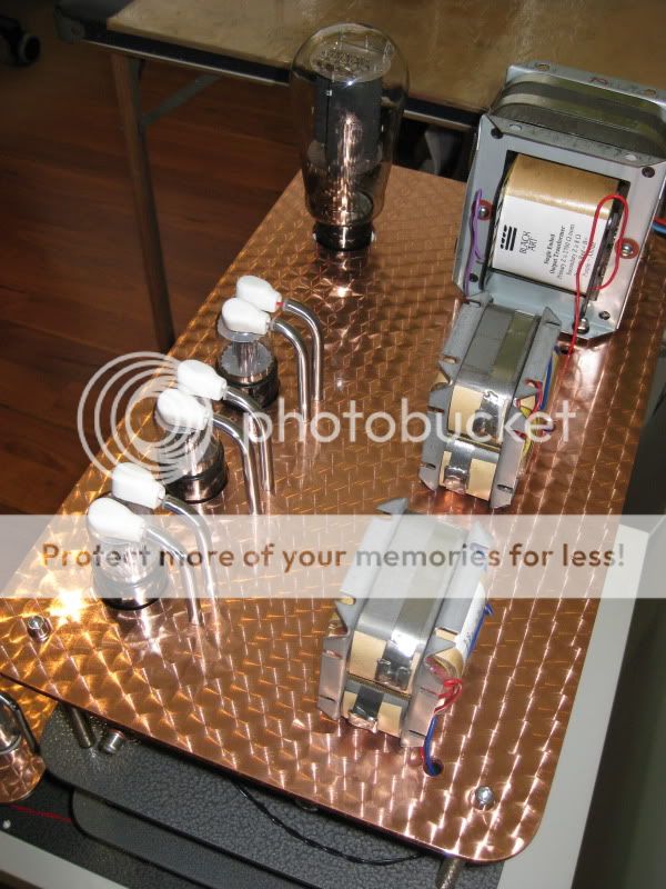
The 3 tubes next to the 300B are 2C22 single triode versions of the 6SN7 and the 4 lower tubes are 6D22 half wave power diodes ,the input/drivers have their own power supply and the 300B has its own reg & power supply .
Cheers
You might want to rethink the design so that no power supply components are anywhere near the audio circuitry.
I have built a significant number of SE amplifiers (both commercial and for personal use) and for quietest operation I have found that placing the power supply on one chassis and the amplifier on another is hard to beat. There will be no issues of electro-static or magnetic coupling between the noisy power supplies and the audio electronics.
I have built a significant number of SE amplifiers (both commercial and for personal use) and for quietest operation I have found that placing the power supply on one chassis and the amplifier on another is hard to beat. There will be no issues of electro-static or magnetic coupling between the noisy power supplies and the audio electronics.
You might want to rethink the design so that no power supply components are anywhere near the audio circuitry.
I have built a significant number of SE amplifiers (both commercial and for personal use) and for quietest operation I have found that placing the power supply on one chassis and the amplifier on another is hard to beat. There will be no issues of electro-static or magnetic coupling between the noisy power supplies and the audio electronics.
Hi Kevin
With chassis 2 the power supplys are 300mm from the top of the power supply and I can flip the filiment suuply power tranny under neither and that will add another 100mm of isolation .I'm also looking at putting dividers in for sheilding .
I could use the same layout but make each section modular and have stand offs connection them .
Cheers
Mal
Last edited:
Good point kevinkr. I would go with 2 separate chassis scheme, one being power supply unit connected with umbilical cord.
Use coax with UHF connectors for the high voltage power umbilical cord. Something like RG213 with PL259 connectors. It's not really safe to run B+ volts outside of a metal chassis unless it is inside a very robust cable (like rg223) or a conduit.
If you are going active with 6 amps, I am assuming you are powering two 3 way speakers? If that is the case, have you thought of optimising your amps to suit the load? The tweeter will require a much smaller amp than the woofer. 300B with associated iron may be wasted on the tweeter and may not powerful enough for the woofer. You may end up with 300B for tweeter and mids with a PP design for woofer etc.
See Rod Elliots site for discussion on bi-amping etc http://sound.westhost.com/bi-amp.htm
Good luck with the project!
Chris
See Rod Elliots site for discussion on bi-amping etc http://sound.westhost.com/bi-amp.htm
Good luck with the project!
Chris
I'd like some advice on this question too. I already build on 2 chassis - the power supply and the signal chassis.
But I've been thinking - why not put the filament supplies on the signal chassis? The transformers - which are toroidal anyway - can be tucked away on one end of the chassis away from the tubes, and the diodes and caps and regulators put right by the tubes.
Advantages of this are:
a) no umbilicals for filament supplies
b) keeps the filament supplies away from the heavy iron in the PSU - mains transformers and chokes.
This is important to me since I use DHT input tubes like 26, 01A etc.
Next question - if you have power in 2 chassis, what do you do with the earth? I was thinking of running a secondary mains lead from the PSU to the signal chassis, so that the switch on for both is in the PSU chassis. So where does the earth go in this arrangement - we have options of the mains cable and the B+ umbilical or both?
Opinions?
Andy
Hi ChrisIf you are going active with 6 amps, I am assuming you are powering two 3 way speakers? If that is the case, have you thought of optimising your amps to suit the load? The tweeter will require a much smaller amp than the woofer. 300B with associated iron may be wasted on the tweeter and may not powerful enough for the woofer. You may end up with 300B for tweeter and mids with a PP design for woofer etc.
[/URL]
Good luck with the project!
Chris
I have seperate 300B amps for the Tweeter different circuit .The OPT's are wound to suit the Raven R1 don't ask me how my mate winds all the trans and its his circuits I'm building .
Cheers
Last edited:
Thanks for the replys guys .
My pre amp has 2 seperate chassis for analog and power supplys mill grade connectors and sheilded umbilical cords much simplar design .
The power amps has 3 power supplys each so I want to keep it all in one vertical chassis .
I should of put the drawings up with the dimensions on you would see theres enough space between the levels plus I can increase the height if needed .
But I will still have a play maybe twin towers with a common based .
Cheers
Mal
To add to chrish's post about P-P amp for woofers, it may have to do with the damping factor of amp and our hearing acuteness (lack of) to lower frequency info. I use active crossover and have 300B SET amp for mid - high frequency driver and Dynaco ST-70 (EL34 P-P) for woofers. Works well.I have seperate 300B amps for the Tweeter different circuit .The OPT's are wound to suit the Raven R1 don't ask me how my mate winds all the trans and its his circuits I'm building .
To add to chrish's post about P-P amp for woofers, it may have to do with the damping factor of amp and our hearing acuteness (lack of) to lower frequency info. I use active crossover and have 300B SET amp for mid - high frequency driver and Dynaco ST-70 (EL34 P-P) for woofers. Works well.
Hi EvenH
I haven't decided what amp to use for the 15" PHL5020 ,we might try one of the 300B SET amps just to see how its sounds with the room speaker combo a couple of friends have PP amp rangine from 2A3 to 6550 .I have a couple of NP F5 boards I might try the speaker is a 4 way .
I should of said in the first post 4 SETs this design and two SETs using a different circuit with a similar chassis design ,so 6 SETs all up for the top section of a 4way and bass drivers amps undecided .
Cheers
Last edited:
If you're putting those amps in cases, you're big problem will be heat. The 6D22's will really warm up everything else, enough so that the rest of the components will have a much shorter life span. Two cases, tubes exposed would be a good approach for long life and reliability.
If you're putting those amps in cases, you're big problem will be heat. The 6D22's will really warm up everything else, enough so that the rest of the components will have a much shorter life span. Two cases, tubes exposed would be a good approach for long life and reliability.
Hi zelgall
The 6D22 will b recessed back into the chassis but not ienclosed in the chassis,this is what I was thinking of .I was worried about people walking up to the amp and kicking the lower tubes .
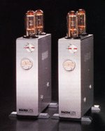
I was thinking of a design cross between Audio Pax and Fi .

Cheers
I guess amplifiers, on the structural level, are only a form of real estate. Where this is scarce we build up. Unfortunately as has been pointed out, heat rises, and whereas in old buildings they put the bedrooms above the kitchen, in the case of tube amps I can't see how the heat could be usefully recycled. Maybe heat could be re-used by some sort of generator that would feed back the energy as electricity? A kind of "green" tube amp?
Andy
Andy
Lots of heavy items up high, I must guess that it is time to think about the outer chassis. Better now than you get down the road. How strong does it need to be? outer perforated skin over strong skeleton? Your drawings are nicely done, I think that is Sketchup, nice free program. How about outer chassis ideas?
Hi firechiefLots of heavy items up high, I must guess that it is time to think about the outer chassis. Better now than you get down the road. How strong does it need to be? outer perforated skin over strong skeleton? Your drawings are nicely done, I think that is Sketchup, nice free program. How about outer chassis ideas?
Yes, google Sketchup beats drawing by hand .
Most of the weight will be low, I'll be using 2mm steel plate for the power supply sections/sheilding and 2mm copper for the top section's around the analog stages .
The I haven't decided on the outer covers just yet do have a few ideas from polished #9 stainless ,nickel coated brass or copper and a candy pearl finish .
A friend can get outer case's CNC folded if I want to go for a steel finish .I can spray the candy finishes over alloy or a timber finish would be nice .
Either way the outer covers will be lighter than the innards.
Cheers
Cheers
Afternoon
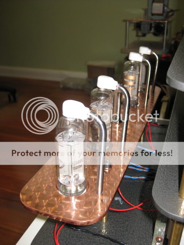
A bit of an update ,I ended up going with a multi layer design .Its almost finished a couple of chokes need to be gapped and the case'ssanded and painted .
Cheers
A bit of an update ,I ended up going with a multi layer design .Its almost finished a couple of chokes need to be gapped and the case'ssanded and painted .
An externally hosted image should be here but it was not working when we last tested it.
An externally hosted image should be here but it was not working when we last tested it.
Cheers
- Status
- This old topic is closed. If you want to reopen this topic, contact a moderator using the "Report Post" button.
- Home
- Amplifiers
- Tubes / Valves
- 300B SET which chassis design