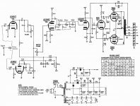
I was looking at the schematic for my bogen chb35a and was wondering if anyone could shed some light on why there is 240/260v going to the cathodes on V2 (12ax7)?
Would anyone have an idea what this voltage is being used for in this amp?
I would like to do some modification after I get it back up and running.. just finished changing the electrolytics and have a hammond 1620 on the way to replace the burt OT..
It just that this is different from anything I have seen (yet) and I would like to understand it a little better if possible lol
Attachments
Greetings,
The 220K and 470 ohm resistor form a voltage divider. The voltage at the cathode will be +.55 volts. They use it for biasing the tube.
Ray
Thanks Ray, that makes more sense to me now
")
Another question I have been struggling with is would it be safe to feed the output of V1a into the grid of V1b as to utilize both stages at once?
I assume that running the output on V1a into the grid of V2b would also mean I would be removing the .1uf cap that is present at the grid currently...
Am I on the right page here or is this going to cause trouble?
I assume that running the output on V1a into the grid of V2b would also mean I would be removing the .1uf cap that is present at the grid currently...
Am I on the right page here or is this going to cause trouble?
Attachments
I'll be using it for guitar eventually, I guess I'm just going for one input more than anything. Would it make more sense to wire a switch between the to halves of the triode on a single input to change from one to the other?
Making it switchable sounds like a better idea to me in terms of guitar use.
If I set it up a three way switch that runs V1a or V1b or both (via one feeding the other or parallel) would there be a way to manipulate the gain in my favor?
Making it switchable sounds like a better idea to me in terms of guitar use.
If I set it up a three way switch that runs V1a or V1b or both (via one feeding the other or parallel) would there be a way to manipulate the gain in my favor?
I just don't get what you want to do. What's wrong with the amplifier as is?
Its not a guitar amp. I intend on modifying it to be so. I'm just looking for a single input that is switchable between "channels" if you will..
The tone stack has Fender values but I think you need to rearrange a couple of parts to make it work. Usually the 250pf capacitor feeds one end of the treble pot and the bass pot connects to the other side of the treble pot. Also if you are trying to use the Fender tone stack look at the factory layout that usually accompanies the schematic. The schematic gets confusing when trying to wire it up. Using the layout will get all of your CW and CCW directions correct.
Craig
Craig
That switch you want to add accomplishes nothing. It switches the input between two equal inputs, so nothing will happen when you do that. Unless your two volume controls are set differently then of course it will revert to whatever the setting was in the other channel.
that's kinda what I'm getting at.. 1st ch/2nd ch/parallel... but instead of a three way I would like to just switch between two channels
With that said is there a way I could do that would increase gain on the 2nd channel?
The tone stack has Fender values but I think you need to rearrange a couple of parts to make it work. Usually the 250pf capacitor feeds one end of the treble pot and the bass pot connects to the other side of the treble pot. Also if you are trying to use the Fender tone stack look at the factory layout that usually accompanies the schematic. The schematic gets confusing when trying to wire it up. Using the layout will get all of your CW and CCW directions correct.
Craig
Thanks Craig I'll give that a try and rework this
Ok, after looking over various Fender schematics I think I might have the tonestack right... also I have added the switch to flip V1A on or off and put what I come to understand is a attenuator after this stage to handle some of the extra gain.. I am just not sure if I have all the values right yet.. I would like to have V1A distort when it is in the signal path but not so much that would not be useable.
Does this look correct or is there something that needs attention?
Does this look correct or is there something that needs attention?
Attachments
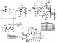
That looks mo better, you can skip the .1uf between the plate and the 250pf capacitor as long as it's voltage rating is high enough. I usually use 500V silvered mica in that location. As far as the input stage goes what is the ultimate goal for the two channels. Are you going to use the 6EU7 or switch to a 12AX7, electronically they are supposed to be the same just different pin out.
Craig
Craig
When I started this I the amp had no tubes so I went ahead and bought new tubes for it.. I thought about the idea of switching the 6EU7 to a 12AX7 but since tonal characteristics differ tube to tube from what I gather I figure keeping the 6EU7 may be interesting..
As far as the two channels go, I'm shooting for one clean channel and one with a high gain (toward distortion) to make it more versatile to my various stlyes of guitar playing..
I'm not quite solid on how to go about it though..
-Mike
As far as the two channels go, I'm shooting for one clean channel and one with a high gain (toward distortion) to make it more versatile to my various stlyes of guitar playing..
I'm not quite solid on how to go about it though..
-Mike
- Status
- This old topic is closed. If you want to reopen this topic, contact a moderator using the "Report Post" button.
- Home
- Amplifiers
- Tubes / Valves
- Bogen chb35a