Hi there,
I am looking for help in changing resistance values in various circuits to get the right voltage at anodes. Advice on the specifics of the design I am working on and/or suggested sources where I can read a bit and understand the basics (which I am clearly lacking) would both be very much appreciated.
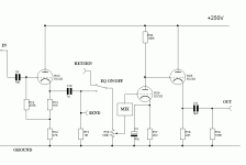
I'm "designing" (in reality patching different circuits together) a tube driven mixer. This will comprise phono stages which will feed into the line-level pre-amp which I have posted below, with the addition of a summing circuit in the box that is labelled "MIX". For the summing circuit, I am planning to use the "Feedback simple tube mixer" design in the following page (it's the third schematic):
The Tube CAD Journal: Vacuum tube mixers
You may note that the schematic asks for 200 volts DC supply, whereas the line-level pre needs 250. In addition, the phono stage needs a 300 volt supply. To my understanding, I therefore need to work with a 300 volt supply and:
A. Add a resistor to the power supply input for the line level pre so that voltage drops to 250 V
B. Change the value of the 10K resistor in the mixer circuit, so that instead of dropping 200V -> 100V as shown in the schematic it allows for a 300V -> 200V drop.
How do I calculate the correct values for the resistors I need for A and B?
Thanks a lot,
Nikos
I am looking for help in changing resistance values in various circuits to get the right voltage at anodes. Advice on the specifics of the design I am working on and/or suggested sources where I can read a bit and understand the basics (which I am clearly lacking) would both be very much appreciated.
I'm "designing" (in reality patching different circuits together) a tube driven mixer. This will comprise phono stages which will feed into the line-level pre-amp which I have posted below, with the addition of a summing circuit in the box that is labelled "MIX". For the summing circuit, I am planning to use the "Feedback simple tube mixer" design in the following page (it's the third schematic):
The Tube CAD Journal: Vacuum tube mixers
You may note that the schematic asks for 200 volts DC supply, whereas the line-level pre needs 250. In addition, the phono stage needs a 300 volt supply. To my understanding, I therefore need to work with a 300 volt supply and:
A. Add a resistor to the power supply input for the line level pre so that voltage drops to 250 V
B. Change the value of the 10K resistor in the mixer circuit, so that instead of dropping 200V -> 100V as shown in the schematic it allows for a 300V -> 200V drop.
How do I calculate the correct values for the resistors I need for A and B?
Thanks a lot,
Nikos
Attachments
Last edited:
- Status
- This old topic is closed. If you want to reopen this topic, contact a moderator using the "Report Post" button.