I have Valve Amplifiers, but not Building Valve Amplifiers. I guess that will be next.
OK, found I had the wrong value resistor in the current sources, LEDs backwards, transformer polarity backwards for GNFB and one transformer set to 60% UL instead of 40%. Other than that it checks out ok.
Sound is really nice after fixing the few mistakes. Base still lacking but to be expected all considering.
Sound-stage is quite good with a good CD, but I'm finding that there is a lot of variance in CDs with this system.
Power, Plenty for easy listening. More than adequate for a computer sound system.
I'm in the den listening to it in the garage.
I've got some wiring to clean up before I can button it up.
I also found that the dual parallel inverse diodes (1N4007) from star ground to chassis cause buzz in both channels, but a 120R resistor does not.
Diodes do not effect both channels equally.
Can anyone explain this?
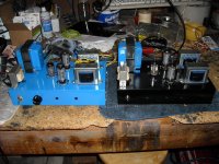
Well, number one is running fine and I started building number two for SWIMBO.
Heaters are wired and verified, star ground and ground isolation ckt is done.
I had a very strange experience with unit number one today.
I was playing Bonnie Raitt Nick of Time (driving Heresy speakers up stairs) and the sound stage was like I was on stage!
Bonnie was to my left and behind me!
Each instrument was well defined and precisely located. I had my eyes closed and could swear I was on stage during a concert (although I've only seen Bonnie live once).
I later playd Bow Wow "New Jack CitY II" (her music, not mine) and the base is quite tight and very pronounce for such a small amp. With good speakers the base is quite acceptable.
Attachments
That's great Steve. It must be quite revealing, since you are hearing "a lot of variance in CDs with this system." This is a good sign  and therefore your CCS on the input tube must be working well too.
Are you still using the schem on post 48? What is the value of R6, 1M or 1K?
SWIMBO, what does the "I" stand for? Have not seen that one before.
Regarding the diodes to chassis ground, I have not had to use that yet, and so far have been doing grounding according to the instructions in this page, scroll down halfway to "grounding".
I really like the 6N1P/6P1P tubes, your suggestion of a PPP version in earlier posts would be an interesting project. I often wonder if PPP makes a better sound, a worse sound, or exactly the same sound but with more power. Due to the averaging of load sharing one might be tempted to think it might sound better? A PPP 6P1P is still a fair bit cheaper than a PP EL84 even after buying the extra sockets, and wouldn't use up much more heater current, that's why I was thinking it would be interesting...since they are a definite nice sounding tube. Ahhh, who knows...
and therefore your CCS on the input tube must be working well too.Are you still using the schem on post 48? What is the value of R6, 1M or 1K?
SWIMBO, what does the "I" stand for? Have not seen that one before.
Regarding the diodes to chassis ground, I have not had to use that yet, and so far have been doing grounding according to the instructions in this page, scroll down halfway to "grounding".
I really like the 6N1P/6P1P tubes, your suggestion of a PPP version in earlier posts would be an interesting project. I often wonder if PPP makes a better sound, a worse sound, or exactly the same sound but with more power. Due to the averaging of load sharing one might be tempted to think it might sound better? A PPP 6P1P is still a fair bit cheaper than a PP EL84 even after buying the extra sockets, and wouldn't use up much more heater current, that's why I was thinking it would be interesting...since they are a definite nice sounding tube. Ahhh, who knows...
R6 is 1M, I can't get LTspice to accept an input of 1M so I use 1000K which it is happy with.
I've tweeked a few things so I'll post the latest schematic with power supply (this won't run under spice because I have several things left out, but it makes a near complete schematic).
I'm using a 1/2A fuse in the input, and the ground isolation is shown.
I miss-typed SWMBO (Phoenetics from the 50s cause me to add vowels to acronyms).
Inputs and outputs are isolated from chassis and grounded at the star ground point.
I don't remember where I found the ground isolation scheme, but if I only use diodes it makes for buzzing in one channel. Why only one channel I don't know but it did the same thing to the PP amp. Adding the shunt Resistor eliminated that and the background noise is now dead silent, even when driving the Heresy.
I wanted to try Schade feedback, but determined that with the current source cranked down to around 1mA and a 100K Schade feedback resistor I would have swamped the current source. I would have to remove the RED LED, and go to a cathode resistor or lower voltage drop LED to use the Schade feedback tecnique. This is something I still want to investigate later on even if I have to abandon the current source/LED bias scheme.
The PPP amp will probably be my next tube project. However, I need to take a break and work on the Ironhead Sportster as it has been setting for 18 months and is getting to be in the way and taking up shelf space.
Attachments
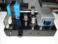
In Post 77 one can see the Current Sources mounted on the 6N1P dual triode with the blue wires running to the power supply board HV connections.
I mounted them this way because I reasoned that the wire to the PS was going to a lower impedance point whereas, if I had mounted the current sources on the PS board and ran the lead from the Current source to the anode of the 6N1P the wire would be connected to high impedances at both ends. Thus this configuration should be less sensitive to noise pick-up.
Logically this makes sense. In reality does it make any difference? It would make for a cleaner layout to mount the current sources on the PS board.
The physical location of the current sources is something I've never thought about, if you were worried about noise pick-up you could use shielded wire perhaps? Thanks for posting the schem, maybe one day I will build one for the workshop at work. Or even better, get the apprentice to build it as part of his "training" that is, if I get one next year. They learn so much from building stuff.
Edit: From what I have read about Schade feedback, one needs to use an input stage tube with high plate resistance for it to work well. That means many triodes in the input stage are not suitable, but many pentodes are suitable (according to what I have read - I'm out of my depth here). Maybe a 12AX7 like in the Baby Huey design is one of few suitable triodes. I am listening to a Baby Huey style amp right now with 6P3S output tubes. The feedback works, no doubt about that. Are you thinking of trying pentode instead of UL at some stage or have you already done that?
that is, if I get one next year. They learn so much from building stuff.Edit: From what I have read about Schade feedback, one needs to use an input stage tube with high plate resistance for it to work well. That means many triodes in the input stage are not suitable, but many pentodes are suitable (according to what I have read - I'm out of my depth here). Maybe a 12AX7 like in the Baby Huey design is one of few suitable triodes. I am listening to a Baby Huey style amp right now with 6P3S output tubes. The feedback works, no doubt about that. Are you thinking of trying pentode instead of UL at some stage or have you already done that?
Last edited:
My understanding of Schade feedback was not that it needed an input stage with a high plate resistance as much as that it would load the output stage less if one were used.
If a high plate resistance of the driving stage were desirable, maybe the 6N2P would be a better choice than the 6N1P. It looks to me like it has a plate resistance near 48K ohms (u=100/S=2.1e-3) compared to 7K (u=33/S=4.7e-3) for the 6N1P.
I've not studied it in depth yet, so I could be wrong.
I tried UL, Pentode and Triode mode with the 6P1P SE, and the wife liked SE with 6-10dB global negative feedback best so that is how I set these up. I may go back and add a switch to mine to be able to select Pentode vs UL for later testing.
Member
Joined 2009
Paid Member
Nice work.
Another idea for open frame output transformer mounting is to take the pressed steel mounting bracket off and cut a hole in the chassis so that you can rotate the transformer such that the electrical connections are below the chassis and the laminations are parallel to the top plate.
Cheers,
Chris
I tried this on my CELLINI amp. I wasted a good chasis by cutting the big square holes first. When I took the pressed steel mounting brackets off the OTs, they promptly fell into pieces. Remember, they are gapped, so there's a big piece of laminated iron held in place by the mounting bracket and nothing else !
Oh my! Thanks for letting us know that Bigun. I'll not try it then. I hope you were able to re-assemble them.
Are there holes in the corners such that one could (carefully) drill through the bracket and still be able to mount the transformers horizontally with screws and nuts?
Next set will probably be built with GXSE10-8-5Ks that should be in this week. I need to get a better power transformer than the Allied ones I used previously. I think I can cut distortion significantly by upping Ik from 36mA to 50+mA. The Allieds were nice and inexpensive, but just not enough current capacity.
Member
Joined 2009
Paid Member
Oh my! Thanks for letting us know that Bigun. I'll not try it then. I hope you were able to re-assemble them.
Luckily, yes. I would suggest keeping the OTs inside the chasis with the power trafo on top - a steel chasis provides some magnetic isolation between them.
I like the tetrode amp. I have some 6E5Ps to play with somewhere...
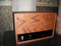
Bump. Wife wasn't happy with a painted metal chassis in the bedroom so I built a Red Oak cabinet for the black amp. I couldn't do a wood bezel as I already had the controls set and they would have been recessed too far.
I have to get some 1-1/4" long 10-32s before I can mount the feet.
I have to get some 1-1/4" long 10-32s before I can mount the feet.
Attachments
- Status
- This old topic is closed. If you want to reopen this topic, contact a moderator using the "Report Post" button.
- Home
- Amplifiers
- Tubes / Valves
- FireFly Single Ended Tetrode