Hey guys.
I was wondering wha other members experience was with a ground plane as advocated by Pete Millett as opposed to the star earth arrangement. I have no doubts at all that Peter knows what he is doing but am worried that when I buid my next amp (6550 set) that it is quite involved to arrange the posts etc for the ground plane and i would hate to have a hum problem which would necessitate a rebuild. Given my basic understanding of some hum being caused by unequal potentials back to earth and given the advocates of star earthing what have other members found when using a ground plane?
Thanks
Nick
Good question")
I like your thing at the bottom, I spoke too much once and lost my job to redundency. My saying now is "Empty drums make the loudest noise"
Pete Millets method is perfect. There was some articals a few years back in EW that went deeply into ground planes. The gist of it was that unless you are thinking of light type frequencies then the ground plane is ideal(it was a long and heated argument, mostly by people who work mainly in theory)
I have found it hard to get the lovely turrets he uses so have used normal turrets so far. I use a piece of plain FR4 and stick all sockets on it. This allows you to have minimal bolts and junk sticking through the top plate. FR4 is another thing as some people say it is hygroscopic and so there will be leakage currents. Who uses PCBs, well everyone and I have never had or heard of a problem. Even MJ mentions this in the 3rd edition.
I use the normal tree type grounding for each section and then all of them to a star ground somewhere convenient for you and on to the PS.
Cheers Matt.
With a star ground, there is exactly one return path for each circuit and exactly one reference point. This is a good thing and works well for audio circuits where the goal is current loop isolation and reduced susceptibility to electromagnetic pickup.
A ground plane has some advantage in potentially lower impedance, but I don't see that as an issue in audio circuits. Ground planes are nice for high speed circuits but still suffer from problems coupling one circuit into another and require careful capacitive decoupling at high frequency. I.e. an output current loop in a ground plane can couple into a nearby input circuit, even if it's not along the "shortest path".
I vote for a star return connection as having a slight advantage in audio.
Michael
Last edited:
Ground plane is fine but DON'T run any current through it - ESPECIALLY AC current. The first filter cap after the rectifier has a large AC (ripple) current through it... return THAT current to the transformer WITHOUT passing through the ground plane and 90% of your hum problems have been solved.
Most hum problems can be traced to the creation of that awful GROUND symbol on the schematic. Not all grounds are equal...
Most hum problems can be traced to the creation of that awful GROUND symbol on the schematic. Not all grounds are equal...
Hey guys.
I was wondering wha other members experience was with a ground plane as advocated by Pete Millett as opposed to the star earth arrangement.
I think it's simple. Any time a current flows through a conductor there is a voltage gradient along the conductor. If you build your ground plane wrong with a speaker's return connection and the transformer's center tap on opposite ends of the plane then you have a good size current flowing across the ground plane. With current in the ground plane all it's points are at different voltages.
I think if you design the ground plane correctly it will look a lot like a star ground made with fat wires
Last edited:
Good point Wavebourne, I guess you mean in a ground plane current(not voltage unless DC) will always take the shortest route?
Why shortest? The whole conductor.
In case of ground plane all things share the same conductor. In case of star ground all of them share conductor that goes from the star to filter capacitor. It is inevitable.
6 of one...
Hey guys
So can i assume that no current into the ground plane means the cathode resistor to the power valves as well? It seems that where you drop to the ground plane influences the result. As an example the speaker ground and the tranny centre tap. So where would one ground the centre tap wrt to the ground plane? It seems the potential (pardon the pun) for capactitance and ground loops is more present in a ground plane than star arrangement.
I think i might use the star as I am least competent at that setup. If i had a tenth of the ability of Pete Millett then I would tackle a ground plane but i dont.
Thanks for the opinions
Nick
Water flows down hill. So does electricity. If you have a narrow channel with big waves and you direct it to a wide plane the water still flows but the waves are reduced in height.
That is about as far as you can take the open water concept and relate it to star and ground planes. Now if you think in terms of length of pipe and pumps the water idea still holds. It is much easier to show with a diagram, might even do it one day.
The electricity does not take the shortest route across the ground plane. It uses the whole thing, your power supply hum is not fussy. The low level signal you are transferring through the ground plane also uses the whole ground plane. Sometimes we can get away with using it for both if the ground plane is big enough and its resistance is so small there is barely a voltage drop across it.
Think in terms of every copper path as a resistor. A star ground where every current has its own circuit path to a common point no longer acts as a true star if there is enough distance between the individual wires at the common point and the current is very much larger through one path as compared to the other. It all comes down to IR. When you share the same R....
Hey guys
So can i assume that no current into the ground plane means the cathode resistor to the power valves as well? It seems that where you drop to the ground plane influences the result. As an example the speaker ground and the tranny centre tap. So where would one ground the centre tap wrt to the ground plane? It seems the potential (pardon the pun) for capactitance and ground loops is more present in a ground plane than star arrangement.
I think i might use the star as I am least competent at that setup. If i had a tenth of the ability of Pete Millett then I would tackle a ground plane but i dont.
Thanks for the opinions
Nick
You may isolate currents that charge filter capacitors both from star and a ground plane, and only the last filter capacitor connect there. That means, the tranny center tap will go to the first capacitor after the rectifier. Then from that capacitor it will go further, depending on how many LC and/or RC filters do you have. And, the finally, the last most filtered point will go by a shortest thickest wire to the common ground where everything is powered from.
What about the additional shielding conferred by a ground plane? Could make a difference for a MC phono amp.
There is no reason that a star ground can't also be a copper fill for shielding. Just make your traces as wide as will fit. For areas where you don't need a ground connection, you can extend copper from a ground trace, but terminating at nothing ... no current to conduct but connected to ground nonetheless. There is no reason that a star ground can't do nearly as good at shielding. The only necessary difference is the gaps between adjacent ground traces.
Thought I was clever
At least for a second. My thought was that if all the star ground leads where equal in length, then there would be no inconsistencies in return paths... but then the IR rule smacked me in the face. Of course something with a huge current (the cathode resistor) would have a different I and therefore V to a wire (same length and therefore R) carrying say cathode current from input tube.
Oh well at least i can deduce that one should use a thicker shorter wire for the bits carrying the highest current. Have I got that right at least?
nick
No need to worry about the wire lengths to the star ground. Because they all terminate at a common point, each path is separate and knows nothing about the others. They need not be "consistent" in length or gauge. Just large enough to handle the circuit's return current.
In other words, the current loops and therefore the IR drops across the individual ground wires are isolated from each other, which is the reason a star ground works.
There is a great paper that covers this from Bill Whitlock but it doesn't seem to be on the Jenssen website anymore.
The DIYaudio thread about star grounding is not very helpful and full of questionable information from a safety and efficacy standpoint.
The best background reading I can find right now is here:
http://www.jensen-transformers.com/an/generic seminar.pdf
I should read all this text linked in this thread to see what's been covered, but wouldn't a major difference with ground plane usage be in some reduction of path inductance because of the spreading of current? Isn't that why the plane conductor performs so much better at high speed? Could it be pictured as a layer of single wires in parallel. With the field rotating around each conductor,it cancels in the adjacent spaces, or elongates the total flux path around the width of the set, dropping field intensity for a given amount of current? Maybe the ground plane isn't so good at eliminating loops, it just spreads them all over, but inductances are minimized. Wheremy goin wrong?
There is no reason that a star ground can't also be a copper fill for shielding. Just make your traces as wide as will fit. For areas where you don't need a ground connection, you can extend copper from a ground trace, but terminating at nothing ... no current to conduct but connected to ground nonetheless. There is no reason that a star ground can't do nearly as good at shielding. The only necessary difference is the gaps between adjacent ground traces.
Agreed.
I do recommend using star return topology on PCB layouts as well. The star ground can be off the PCB with a separate return wire from each circuit on the PCB to the ground star.
If the circuit is already inside a metal enclosure, there might no be need for additional Faraday shielding.
Michael
Attachments

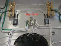
Wheremy goin wrong?
Nowhere, mon frere
I just think that in audio circuits loop isolation is way more important than low impedance. It's a simple IR voltage drop in the return path, Ohm's law will suffice, no need for Maxwell's other equations.
In e.g. high speed digital circuits the low impedance, particularly inductance, trumps the question and loop isolation becomes the problem to be solved through decoupling and layout.
Michael
Interesting. With power amplifiers I am fully agree. The risk is to big that the big amplifier currents get modulated into the low level line, with hum as result. In a power amplifier design with mixed high and low current, you want to have more "control" over where those ground currents flow. This is indeed more important then a low ground impedance. I would always go for star grounding in a power amplifier. One could experiment with different ground planes. One for power and one for line, but then be sure they are not exact the size on the overlapping layers.
For line level applications, I do recommended ground planes though (like pre-amps, D/A converter output stages etc.)
With kind regards,
Bas
Hasn't anyone written a layout software that puts the calculus on this, to make the most of available copper, looking at increases in parasitic capacitances and the whole ball of wax? I guess it would have to be an integrated simulator that actually looked at circuit performance. Extremely complicated.
Last edited:
- Status
- This old topic is closed. If you want to reopen this topic, contact a moderator using the "Report Post" button.
- Home
- Amplifiers
- Tubes / Valves
- Ground Plane vs Star earth