If you have a schematic, you could post it here and we could answer your question more easily. If not, there are three key numbers you will need to know. First is plate voltage and second is cathode voltage and the third is the resistance of the cathode resistor that (I think) you are measuring that "bias voltage" across.
I don't know your level of experience, but directly measuring the plate voltage could get you killed. You might want to inquire of the manufacturer that spec. The bias resistor value you can measure with a volt/ohm meter. Simply turn off the amp and wait a couple of minutes. Then place the probes of the VOM into the bias ports like you did when you measured the voltage, but this time measure the resistance.
Now, you can use ohms law to calculate cathode current from that voltage number. Divide the voltage figure you measured by the resistance. The result is amps. Multiply by 1000 and you have milliamps.
Then you multiply the cathode current by the difference between plate voltage and cathode volatge. That's power in watts. Let's say the plate voltage is 350volts higher than the cathode (and I have no idea the real number) and the idle current is 60 ma. Then the power is 350 * .060 or 21 watts. You want to operate your tubes at about 70% maximum power at idle because they will produce more power at volume. They reach peak power at normal listening levels and then actually fall of some at higher levels.
This calculator is helpful. Weber Bias Calculator
Last edited:
Bias
Thanks dave, I measured the volts using probe holes at both sides of amp, it says 1.15V above these and you can adjust the bias via a screw. My mate, who's as silly as me, told me to bump up the bias voltage at idle here. When I first measured it numbers were jumping from 1.2 to 1.4 on each tube in the quad, I adjusted until all four sat at 1.3, thought this was ok. Your extra info is great, thanks for taking the time to explain. Cheers.
Thanks dave, I measured the volts using probe holes at both sides of amp, it says 1.15V above these and you can adjust the bias via a screw. My mate, who's as silly as me, told me to bump up the bias voltage at idle here. When I first measured it numbers were jumping from 1.2 to 1.4 on each tube in the quad, I adjusted until all four sat at 1.3, thought this was ok. Your extra info is great, thanks for taking the time to explain. Cheers.
Thanks dave, I measured the volts using probe holes at both sides of amp, it says 1.15V above these and you can adjust the bias via a screw. My mate, who's as silly as me, told me to bump up the bias voltage at idle here. When I first measured it numbers were jumping from 1.2 to 1.4 on each tube in the quad, I adjusted until all four sat at 1.3, thought this was ok. Your extra info is great, thanks for taking the time to explain. Cheers.
Never good to do something without some understanding of what you are doing and why. Without knowing the resistance of that cathode resistor and the plate voltage applied to the output tube you cannot determine whether or not you are running the tube beyond its plate dissipation rating.
Running a tube beyond its plate dissipation rating can have serious consequences ranging from shortened output tube life to catastrophic failure with the potential for significant to serious damage to the amplifier itself. Doing so also significantly increases the load on the power supply and you had better be sure that the supply can handle the increased current.
Unless your mate designed the amplifier in question and knows it is safe to increase the idle current I would set it back to the recommended level until you have done your homework.
In one or two instances where a misguided client damaged his amplifier doing this I had to void the warranty (I clearly stated that deliberate operation outside of maximum limits would void the warranty - and this limiting value was well beyond my recommended operating conditions btw) - you might want to think about that in the event your amp is still under warranty. Consult with the designer/manufacturer!
Doing this might make the amplifier sound and measure better, but before you do you need to know it is safe to do so, otherwise it is just foolish...
Thank you for pointing out that I am an idiot. I have returned volts to factory level. Now, I have another question, is it ok to stick a fork into a toaster while toasting a crumpet?
It could prove to be "quite" interesting, but haven't we all done that or something similar at one time or other?
")
(I have done just that, well into the crumpet anyway, and got away with it somehow or other..
)I second what kevinkr said in his first post. There is an excellent chance that the manufacturer has specified the correct bias. It is, after all, in his best economic interest to see the tubes operate through the warranty period while producing hi-fi sound. Your interests are aligned.
Until you know all of the parameters, increasing bias will only ruin those new tubes. That said, post the voltages and resistances when you learn them.
Until you know all of the parameters, increasing bias will only ruin those new tubes. That said, post the voltages and resistances when you learn them.
Melody Schematics
I tracked down schematics for the SP3, does this help in answering my question about correct bias for 6l6GC power tubes? I'm still running them at factory 1.15V. I've also included an interior image.
I tracked down schematics for the SP3, does this help in answering my question about correct bias for 6l6GC power tubes? I'm still running them at factory 1.15V. I've also included an interior image.
Attachments
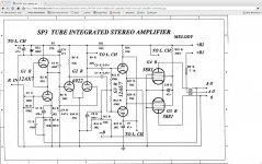
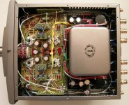
It's chinese, branded Australian. I'm pretty sure this is the amps schematic, not a schematic kind of guy so I'm relying on my source and the title printed on schematic! You can measure the cathode bias via probe holes, four in all, on left and right side of amp, just in front of the vents, you can see this in the interior photo. How this corresponds to schematic I don't know.
there is a bit more here
http://www.diyaudio.com/forums/tubes-valves/153690-onix-melody-sp3-upgrades-mods.html
http://www.diyaudio.com/forums/tubes-valves/153690-onix-melody-sp3-upgrades-mods.html
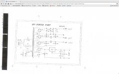
Schematic Melody SP3 MK2 + power supply
Help! I have a Melody SP3 Mk2. And as I was going over my files, it turns out I may have the schema for the Mk2---it includes the bias circuits 2/channel.
Here is my problem. My SP3 toasted a rather large 470 ohm resistor (5watt?) which appears to be R19 in the attached schema. Since it is close to the 5881 tubes ( in the pictures posted by another member, its opposite the vol. control closer to the power transformers) I took out the power tubes first thinking its a shorted tube although the 33 ohm resistors grounding the cathodes seem fine. I found 470 5watt in my junk box so I soldered that in. Without the tubes, I turned on the power. Instantly, that 470 got got fried. Does anyone have any suggestions on what to look into, before I take it to a more knowledgeable tech. Thank you very much for any suggestions
Tulisan
Attachments
Problem with Melody SP3, mk2
My SP3 toasted a rather large 470 ohm resistor (5watt?) which appears to be R19 in the attached schema. Since it is close to the 5881 tubes ( in the pictures posted by another member, its opposite the vol. control closer to the power transformers) I took out the power tubes first thinking its a shorted tube although the 33 ohm resistors grounding the cathodes seem fine. I could only find a 470 5watt in my junk box so I soldered that in. Without the tubes, I turned on the power. Instantly, that 470 5watt got fried. Does anyone have any suggestions on what to look into, before I take it to a more knowledgeable tech. Thank you very much for any suggestions
I am attaching the Schematic for the Melody SP3 Mk2
Attachments
Thank you PRR. Locating components on the SP3 aside from the more obvious ones are a PIA very crowded plus printed circuit board I have vintage fishers that I refurbished. In comparison, it was super easy to ID components since it is point to point wired, and all I had to do was start at a known point, eg., power tube pin, and trace from there. PC boards, esp double sided are the worse. Its enough for me to just junk the SP3, or rebuild using P to P. Problem is, while the schematic shows components of R-Cs it does not show ratings, eg., watts or volts. so one cannot even begin to source parts. One might be able to figure out some capacitors since they are labeled. but those red chinese resistors only have printed r value, no ratings. For now I will store the SP3 in garage so I don't have to look at it. I have enough vintage amps, a fisher x-101-c, a 500c where I pulled out all the tuner related tubes and just using it as a big brother amp to the x-101-c, plus a VTA moded Dynaco ST70. If anything goes wrong, easy to fix by slinging solder, and thanks to the expertise and experience of members here at DIY Audio. Thank you all!
- Home
- Amplifiers
- Tubes / Valves
- Melody Roll