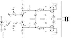
I created this amp from scratch, using only parts I had laying around.
It's the first (decent) amp I designed so I'd like some feedback from the tube-guru's to what I did good/wrong
It's not very sensitive, but it's designed to work with my preamp.
B+ = 300V
B++ = 268V
-Ubias = -42V
datasheets here:
http://www.tubes.mynetcologne.de/roehren/daten/el36pentode_as_triode_v2.pdf
http://www.mif.pg.gda.pl/homepages/frank/sheets/030/p/PCC85.pdf
Attachments
I like it !
Wich B+ and B++ values ?
Just for chatting, you may increase (double or triple) the values of R15 / R16 and lower C1 / C2 by the same proportion.
Congratulations !
Yves.
Thanks, the values of B+ and B++ are in the first post, around 300V and 265V
I did not really calculate the values for the coupling capacitors, I just happen to have a large bag of phillips mustard capacitors i bought really cheap.
I lend my book with all the formulas (Morgan Jones, valve amplifiers) and dont know the formullas of the head. I just used values wich made the amp sound good.
Later today, I replaced the UCC85 with an ECC88, wich is far more lineair in the used region, but has even less gain. (and higher price)
Radiostar:
It's still a protype, so I used a pair of bench supply's to power the heaters.
A benefit of using a UCC85 is it can be placed in parallel with both PL36 heaters
so only a 25V heater supply is needed.I used a cheap 230V isolation transformer for the B+, together with a 15H choke I got together with the Jukebox Iron (from an old seeburg, sounds actually very good!)
If anyone is interessed, I might draw the power supply schematic tomorrow.
IRFP450 have a VERY high input capacitance, which is also somewhat non-linear - although this is helped out by the fact you normally have quite a bit of voltage between D and G. However, this nonlinearity will become apparent when you drive the output hard enough to have less than about 6-8V between G and D of either MOSFET. These are high current parts (14A), which you really don't need in your application. IRF820 (on a heatsink, of course) should do much better here - it's a 2.5A part which also has proportionally lower capacitances compared to the IRFP450. There are even better choices in the 2SK*** camp. Also, be sure to put protection zeners across G-S of each MOSFET - the way it's connected now, driving your amp to clipping will kill the MOSFETs due to overvoltage between G and S - MOSFETs are VERY sensitive to this.
Last edited:
Thanks for the info ilimzn, I just picked some mosfets I had laying around.
I figured the capacitance didnt matter much in this circuit?
I will add the zeners, it's not because they where free, I want to destroy them
Are there other important parameters of the mosfets besides the input capacitance and Max Drain-Source voltage I should care about? how about power?
I figured the capacitance didnt matter much in this circuit?
I will add the zeners, it's not because they where free, I want to destroy them
Are there other important parameters of the mosfets besides the input capacitance and Max Drain-Source voltage I should care about? how about power?
After reading a bit about screen driving (Synola SE 509, also read the PDF article) I decided to give screen driving the EL36/PL36/6CM5/6P31S... a try.
I found the curves for screen driven EL36 on Tom Schlangen's Homepage
I have attached my newest brainchild here (B+ is 320V)
The potentiometer in the CSS is used to set up the BIAS of the whole amplifier. The other potentiometer is used to balance the output tubes.
I used -24V on Grid1 of the output tubes because I had it available in the prototype
It doesnt really sound as good as expected, tips to improve that are very welcome
PS: sorry for the crappy CSS placing on my schematic.
Attachments
It doesnt really sound as good as expected, tips to improve that are very welcome
From the Tom Schlangen datasheet: "CF driver for screen must be able to source at least 15-20mA at Eg2 = 200V". Maybe I am misreading your schematic but your source follower does not have enough current (3-4mA ???).
A couple more ideas from the armchair
1. You could replace R9 / R10 by current sources which might further improve the source followers.
2. Allen Wright would tell you to convert the output stage into a truly differential amplifier by biasing it from a current source. The tricky bit is then to get the current through both halves equal. One possibility would be to use some kind of autobias, which could potentially be done via G1.
My 2 cents.
I am currently happy with the means of biasing and balancing the valves, it is also not the cause of the awful distortion at higher volume I believe.
At low volume, the amp sounds pretty sweet.
My power supply however is one of the limiting factors right now (I'm using a tube rectifier, EZ81)
When I crank up the amp, B+ is only 290V and B++ 250V.
You must be right about the source followers however, I mistakenly figured the current in G2 would flow from B+ throug the mosfet, through the tube, to GND.
Since it's obviously flowing the other direction, using P-mosfets could solve that problem I guess.
The IRFU9310PBF looks good on paper to me (and also the price hehe)
Too bad i dont have any laying around to try right now..
EDIT: or am i now mistaken about the current again?
Last edited:
EDIT: or am i now mistaken about the current again?
Unless I am mistaken you are mistaken. If your source follower has a DC bias of say 4 mA it should be able to swing between 0 and 8 mA, but not beyond. Nothing to do with P or N channel.
Unless I am mistaken you are mistaken. If your source follower has a DC bias of say 4 mA it should be able to swing between 0 and 8 mA, but not beyond. Nothing to do with P or N channel.
It is a source follower, not a common cathode (or with mosfets, common source) amplifer.
The current you are talking about is the current throug the resistor.
It has nothing to do however with the current the source-follower can sink/source. In case of a N-channel mosfet, it will be able to source a lot of current (from B+), when using a P-channel mosfet, you will be able to sink the current (to GND)
Because a schematic says more then a thousand words, I attached a rudimentary schematic wich should explain my previous post.
(The left schematic will work perfectly, but the right not, because the mosfet cannot provide the negative current needed)
Now my question was if the current in grid2 is flowing as in the left schematic, or the right.
Attachments
I mistakenly figured the current in G2 would flow from B+ throug the mosfet, through the tube, to GND.
Since it's obviously flowing the other direction, using P-mosfets could solve that problem I guess.
Hmm I think you got it backwards. By convention current flows from a higher potential to a lower, from + to -. (the elecrons them self don't not care however)
So I would definetly stick with the N-channel device.
/Olof
It has nothing to do however with the current the source-follower can sink/source.
You are right, it can off course supply more current, my bad. It would be the picture on the left, except you have the polarities of the 20 mA current source reversed. Current (arrow) flows into the control grid.
However, I still think you have an issue with the very low current you are running thru the follower:
The output impedance should be roughly the reciprocal of the transconductance of the FET. I think the current thru the grid varies greatly with grid voltage (signal swing), so does the follower's output impedance, especially since the transconductance curve is steepest at the low currents. Furthermore, the current through the 47K resister also varies in phase with the control grid current, increasing the current swing.
A higher bias plus a current source would really help, at least in my book.
Yes, you guys are right, got the current direction right the first time, no more beer for me hehe. I've measured the gate-source voltage of the mosfet with my O'sope, and it indeed doesnt look very pretty.
My prototype has 27k resistors instead of the 47k as on the schematic, but perhaps the current source is a good idea indeed.
(sorry for being so bitchy, but I didnt want to unnescessary complicate the schematics, or implement changes of wich i dont understand how they will improve the system, without understanding exactly how.)
I'm using power supply mosfets right now, wich have pretty high input capacitance, but do have a very high transconductanse.. time to experiment)
To quote another forum member: "All just for fun."
Running Screen drive connected Sweep tubes with Ug1 = -18V looks like some limitation for high volume use.
The curves for the 6П31С (Russian 6P31S sweep tube) that you have on the schematic indicate a peak current of only about 100mA for any anode voltage (for Ug2= 170V ).
Other experimenters here believe Ug1=0 to be the best setting, but I recall George(Tubelab) mentioning the hazard that screen current becomes too high when the anode voltage falls LOW.
In this case, some protection against screen burnout is needed. But this should not be difficult: just add a 2-transistor current-limit in the dc supply to the screens.
You could use auto-bias on G1. Also, as Rod Coleman says, Vg1=-24V decreases available plate current.
Regarding MOSFETs, the reverse transfer capacitance will be paramount here, while there is way more Gm than you can use - in other words use the appropriate voltage MOSFETs (400V should be fine), but relatively low current, IRF710 if you can find it, is a good choice. The increasing transconductance with increasing source current actually helps the follower maintain gain closer to 1, which is something you want.
Your schematic has one drawback, and that is the bias and swing depends on the operating point of the input tubes. This is no trivial matter as change of input tube current also changes the ability to drive the MOSFET. Even though it looks nice to use DC coupling throughout, if you want to do it, you might end up with choosing the input tube in order to satisfy bias and swing requirements.
If i were you, I would AC couple the source follower gates, and DC bias them from a varible voltage (a simple pot divider and resistors to each gate whould o fine). Then, once satisfied with the sound a particular setting gives me, investigate if i can (re)design the input stage to offer the same swing and DC bias so the follower can be used direct coupled.
And... don't forget the zeners
I have ditched the EZ81 for a solid-state rectifier and hooked the G1's of the output tubes to a variable power supply. The source followers are also AC-coupled right now. But I havent been able to out-perform the previous version of the amp (wich used triode-connected 6p31s)
Looks like the source followers are the bottleneck atm, when the voltage swing (and g2 current) rise above a certain level, the distortion caused by them rises very fast.
Maybe this circuit would better work with EL36/PL36 instead of the smaller 6p31s.
ilimzn: with auto bias, do you mean connecting G1 to GND and using larger cathode resistors (decoupled perhaps) ? If so, it could be used in final version, but variable power supply is easier to find the 'sweet spot'
I'll keep you guys informed..
- Status
- This old topic is closed. If you want to reopen this topic, contact a moderator using the "Report Post" button.
- Home
- Amplifiers
- Tubes / Valves
- My new PL36 Push-Pull amp